background image

Figure 40

6.

Remove the dust cap and adjust the caster pivots.
Keep the dust cap off until greasing is done. Refer to
Adjusting the Caster Pivot Bearing in Maintenance.

7.

Remove the hex plug. Thread a grease zerk into the
hole.

8.

Pump grease into the zerk until it oozes out around
the top bearing.

9.

Remove the grease zerk in the hole. Install the hex plug
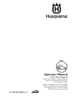
and dust cap (Figure 41).

g014942

Figure 41

Lubricate the Caster Wheel
Hubs

Service Interval:

Yearly

1.

Stop the engine, wait for all moving parts to stop, and
remove the key. Engage the parking brake.
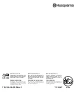
Figure 42

1.

Seal guard

2.

Spacer nut with wrench
flats

2.

Remove the caster wheel from the caster forks.

3.

Remove the seal guards from the wheel hub.

4.

Remove 1 of the spacer nuts from the axle assembly in
the caster wheel. Note that thread locking adhesive
has been applied to lock the spacer nuts to the axle.
Remove the axle (with the other spacer nut still
assembled to it) from the wheel assembly.

5.

Pry out the seals, and inspect the bearings for wear or
damage and replace if necessary.

6.

Pack the bearings with a general-purpose grease.

7.

Insert 1 bearing and 1 new seal into the wheel.

Note:

The seals must be replaced.

8.

If the axle assembly has had both spacer nuts removed
(or broken loose), apply a thread locking adhesive to 1
spacer nut and thread it onto the axle with the wrench
flats facing outward. Do not thread the spacer nut all of
the way onto the end of the axle. Leave approximately
3 mm (1/8 inch) from the outer surface of the spacer
nut to the end of the axle inside the nut.

9.

Insert the assembled nut and axle into the wheel on the
side of the wheel with the new seal and bearing.

10.

With the open end of the wheel facing up, fill the area
inside the wheel around the axle full of general-purpose
grease.

11.

Insert the second bearing and new seal into the wheel.

12.

Apply a thread locking adhesive to the second spacer
nut and thread it onto the axle with the wrench flats
facing outward.

13.

Torque the nut to 8-9 N-m (75-80 in-lb), loosen, then
re-torque to 2-3 N-m (20-25 in-lb). Make sure that the
axle does not extend beyond either nut.

30

Summary of Contents for 74956

Page 1: ...o 3375 659 Rev C Z Master Commercial 3000 Series Riding Mower with 60in TURBO FORCE Side Discharge Mower Model No 74956 Serial No 313000001 and Up Register at www Toro com Original Instructions EN 3375 659 C ...

Page 2: ...inal Toro parts The enclosed Engine Owner s Manual is supplied for information regarding the US Environmental Protection Agency EPA and the California Emission Control Regulation of emission systems maintenance and warranty Replacements may be ordered through the engine manufacturer Introduction This rotary blade riding lawn mower is intended to be used by residential homeowners or professional hi...

Page 3: ...ervicing the Engine Oil 32 Servicing the Spark Plug 35 Check Spark Arrester if equipped 36 Fuel System Maintenance 37 Servicing the Electronic Fuel Injection System 37 Replacing the Low Pressure Fuel Filter 37 Servicing the High Pressure Fuel Filter 37 Servicing the Fuel Tank 37 Electrical System Maintenance 38 Servicing the Battery 38 Servicing the Fuses 40 Drive System Maintenance 40 Checking th...

Page 4: ... functioning properly Operation Lightning can cause severe injury or death If lightning is seen or thunder is heard in the area do not operate the machine seek shelter Never run an engine in an enclosed area Only operate in good light keeping away from holes and hidden hazards Be sure all drives are in neutral and parking brake is engaged before starting engine Only start engine from the operator ...

Page 5: ...t drives mufflers and engine to help prevent fires Clean up oil or fuel spillage Let engine cool before storing and do not store near flame Shut off fuel while storing or transporting Do not store fuel near flames or drain indoors Park machine on level ground Set parking brake Never allow untrained personnel to service machine Use jack stands to support components when required Carefully release p...

Page 6: ... degrees Use the slope chart to determine the degree of slope of hills before operating Do not operate this machine on a slope greater than 15 degrees Fold along the appropriate line to match the recommended slope 2 Align this edge with a vertical surface a tree building fence pole etc 3 Example of how to compare slope with folded edge 6 ...

Page 7: ...afety decals and instructions are easily visible to the operator and are located near any area of potential danger Replace any decal that is damaged or lost 1 403005 54 9220 58 6520 1 Grease 66 1340 68 8340 98 5954 103 2076 105 7798 7 ...

Page 8: ...107 2102 109 7232 1 Fast 3 Neutral 2 Slow 4 Reverse 110 2067 110 2068 1 Read the Operator s Manual 114 4466 1 Main 25A 3 Charge 25A 2 PTO 10A 4 Auxiliary 15A 8 ...

Page 9: ...nd spindles 2 Maintenance interval 50 hours 116 0205 116 0211 116 0752 1 Latch 2 Unlatch 116 1654 116 1716 1 Fuel 6 Hour meter 2 Empty 7 PTO 3 Half 8 Parking brake 4 Full 9 Neutral 5 Battery 10 Operator presence switch 116 2643 9 ...

Page 10: ...n flame or smoking 7 Wear eye protection explosive gases can cause blindness and other injuries 3 Caustic liquid chemical burn hazard 8 Battery acid can cause blindness or severe burns 4 Wear eye protection 9 Flush eyes immediately with water and get medical help fast 5 Read the Operator s Manual 10 Contains lead do not discard Manufacturer s Mark 1 Indicates the blade is identified as a part from...

Page 11: ...ppears when the fuel level is low approximately one gallon remaining in the fuel tank Safety Interlock Indicators There are symbols on the hour meter and the indicate with a black triangle that the interlock component is in the correct position Figure 6 Battery Indicator Light If the ignition key is turned to the On position for a few seconds the battery voltage will be displayed in the area where...

Page 12: ...ole panel Once the MIL illuminates initial trouble shooting checks should be made Refer to the MIL section under Toubleshooting If these checks do not correct the problem further diagnosis and servicing by an Authorized Service Dealer is necessary Attachments Accessories A selection of Toro approved attachments and accessories is available for use with the machine to enhance and expand its capabil...

Page 13: ...in conditions during fueling static electricity can be released causing a spark which can ignite the gasoline vapors A fire or explosion from gasoline can burn you and others and can damage property Always place gasoline containers on the ground away from your vehicle before filling Do not fill gasoline containers inside a vehicle or on a truck or trailer bed because interior carpets or plastic tr...

Page 14: ... of break in time for new machines to develop full power and best performance Using the Rollover Protection System ROPS WARNING To avoid injury or death from rollover keep the roll bar in the fully raised locked position and use the seat belt Ensure the seat is secured to the machine WARNING There is no rollover protection when the roll bar is in the down position Lower the roll bar only when abso...

Page 15: ...could help you or bystanders avoid injury DANGER Operating on wet grass or steep slopes can cause sliding and loss of control Wheels dropping over edges can cause rollovers which may result in serious injury death or drowning There is no rollover protection when the roll bar is down Always keep the roll bar in the fully raised and locked position and use the seat belt Read and follow the rollover ...

Page 16: ...Setting the Parking Brake WARNING Parking brake may not hold machine parked on a slope and could cause personal injury or property damage Do not park on slopes unless wheels are chocked or blocked G016994 1 2 Figure 11 Releasing the Parking Brake G016995 1 2 Figure 12 Operating the Mower Blade Control Switch PTO The blade control switch PTO starts and stops the mower blades and any powered attachm...

Page 17: ... for the first time after the fuel system has been without fuel completely STA RT RU N STO P G008947 Figure 16 2 Turn the ignition key to stop to stop the engine Using the Fuel Shut Off Valve The fuel shut off valve is located under the seat Move the seat forward to access it Close the fuel shut off valve for transport maintenance and storage Ensure the fuel shut off valve is open when starting th...

Page 18: ...U N STO P G008947 Figure 19 1 Off 3 Start 2 Run Stopping the Engine CAUTION Children or bystanders may be injured if they move or attempt to operate the machine while it is unattended Always remove the ignition key and set the parking brake when leaving the machine unattended even if just for a few minutes Let the engine idle at slow throttle turtle for 60 seconds before turning the ignition switc...

Page 19: ...nd move the blade control switch PTO to on Try starting the engine the engine should not crank 2 Sitting on the seat engage the parking brake and move the blade control switch PTO to off Move either motion control lever out of neutral locked position Try starting the engine the engine should not crank Repeat for other control lever 3 Sitting on the seat engage the parking brake move the blade cont...

Page 20: ...brake engaged To stop pull the motion control levers to the neutral position 1 Release the parking brake refer to Releasing the Parking Brake in Operation 2 Move the levers to the center unlocked position 3 To go forward slowly push the motion control levers forward Figure 23 G008952 Figure 23 Driving Backward 1 Move the levers to the center unlocked position 2 To go backward slowly pull the motio...

Page 21: ...perate the machine while it is unattended Always remove the ignition key and set the parking brake when leaving the machine unattended even if just for a few minutes Adjusting the Height of Cut Using the Transport Lock The transport lock has two positions and is used with the deck lift pedal There is a lock position and a unlock position for the transport position The transport lock is used with t...

Page 22: ...ed and insert the pin Figure 26 5 Push on the deck lift pull back on the transport lock and slowly lower the mower deck 1 3 2 G017027 Figure 26 1 Deck lift pedal 3 Transport lock 2 Cut of height pin Adjusting the Anti Scalp Rollers Whenever you change the height of cut it is recommended to adjust the height of the anti scalp rollers 1 Disengage the blade control switch PTO move the motion control ...

Page 23: ... back over to tighten the baffle and cam locks Figure 30 6 If the cam locks do not lock the baffle into place or it is too tight loosen the lever and then rotate the cam lock Adjust the cam lock until the desired locking pressure is achieved G008961 1 2 3 4 Figure 30 1 Unlock lever 3 Position the baffle 2 Rotate the cam lock to increase or decrease locking pressure 4 Lock lever Positioning the Flo...

Page 24: ...p before accessing the drive wheel release valves WARNING The engine and hydraulic drive units can become very hot Touching a hot engine or hydraulic drive units can cause severe burns Allow the engine and hydraulic drive units to cool completely before accessing the drive wheel release valves The drive wheel release valves are located in the back of each hydraulic drive unit under the seat Note M...

Page 25: ...mps to simulate a full width continuous ramp The ramp should be long enough so that the angles do not exceed 15 degrees Figure 36 A steeper angle may cause mower components to get caught as the unit moves from ramp to trailer or truck Steeper angles may also cause the unit to tip backward If loading on or near a slope position the trailer or truck so it is on the down side of the slope and the ram...

Page 26: ...or a slow moving vehicle emblem is dangerous and can lead to accidents causing personal injury Do not drive machine on a public street or roadway To transport the machine 1 If using a trailer connect it to the towing vehicle and connect the safety chains 2 If applicable connect the trailer brakes 3 Load the machine onto the trailer or truck 4 Stop the engine remove the key set the brake and close ...

Page 27: ... frequently If you cannot mow for an extended period first mow at a high cutting height then mow again two days later at a lower height setting Cutting Speed To improve cut quality use a slower ground speed in certain conditions Avoid Cutting Too Low If the cutting width of the mower is wider than the mower you previously used raise the cutting height to ensure that uneven turf is not cut too shor...

Page 28: ...nlet screen Every 200 hours Change the engine oil filter Clean the engine oil cooler Check clean and regap the spark plug Replace the fuel filter more often in dirty or dusty conditions Every 250 hours Change the hydraulic filters and hydraulic oil when using Mobil 1 oil more often in dirty or dusty conditions Every 300 hours Replace the primary air filter more often in dusty or sandy conditions C...

Page 29: ... to ooze out of the bearings 5 Wipe up any excess grease Where to Add Light Oil or Spray Lubrication Service Interval Every 100 hours Lubricate the deck lift pivots G017028 Figure 38 Where to Grease the Mower Service Interval Every 50 hours Grease the mower deck spindles and idler arm Yearly Grease the pump belt idler arm Yearly Grease the front caster pivots more often in dirty or dusty condition...

Page 30: ...Pry out the seals and inspect the bearings for wear or damage and replace if necessary 6 Pack the bearings with a general purpose grease 7 Insert 1 bearing and 1 new seal into the wheel Note The seals must be replaced 8 If the axle assembly has had both spacer nuts removed or broken loose apply a thread locking adhesive to 1 spacer nut and thread it onto the axle with the wrench flats facing outwa...

Page 31: ...uently if the operating conditions are extremely dusty or sandy Removing the Filters 1 Disengage the PTO move the motion control levers to the neutral locked position and set the parking brake 2 Stop the engine remove the key and wait for all moving parts to stop before leaving the operating position 3 Release the latches on the air cleaner and pull the air inlet cover off the air cleaner body Fig...

Page 32: ...er the inner filter Figure 44 Note Ensure that the primary filter is fully seated by pushing on its outer rim while installing it Important Do not press on the soft inside area of the filter 4 Install the air cleaner cover and secure the latches Figure 44 Servicing the Engine Oil Oil Type Detergent oil API service class SJ or higher Oil Capacity with a filter change 58 ounces 1 7 L with no filter ...

Page 33: ...ling center 1 Park the machine so that the rear is slightly lower than the front to ensure the oil drains completely 2 Disengage the PTO move the motion control levers to the neutral locked position and set the parking brake 3 Stop the engine remove the key and wait for all moving parts to stop before leaving the operating position Figure 47 G008804 G008793 1 2 3 4 4 5 Figure 47 33 ...

Page 34: ... filter more frequently when operating conditions are extremely dusty or sandy 1 Drain the oil from the engine refer to Changing the Engine Oil 2 Change the engine oil filter Figure 49 G008804 G008748 3 4 1 2 3 4 5 6 Figure 49 Note Ensure the oil filter gasket touches the engine and then an extra 3 4 turn is completed 3 Fill the crankcase with the proper type of new oil refer to Changing the Oil S...

Page 35: ...ark plug s if necessary Type Champion XC12YC or equivalent Air Gap 0 030 inch 0 76 mm Removing the Spark Plug 1 Stop the engine remove the key and wait for all moving parts to stop before leaving the operating position 2 Disengage the PTO move the motion control levers to the neutral locked position and set the parking brake 3 Remove the lefthand hydraulic unit shroud in the order listed with Figu...

Page 36: ...very 50 hours WARNING Hot exhaust system components may ignite gasoline vapors even after the engine is stopped Hot particles exhausted during engine operation may ignite flammable materials Fire may result in personal injury or property damage Do Not refuel or run engine unless spark arrester is installed 1 Stop engine wait for all moving parts to stop and remove key Engage parking brake 2 Wait f...

Page 37: ... brake 2 Stop the engine remove the key and wait for all moving parts to stop before leaving the operating position 3 Allow the machine to cool down 4 Stop the engine remove the key and wait for all moving parts to stop before leaving the operating position 5 Close the fuel shutoff valve under the seat Figure 55 G008963 1 2 3 Figure 55 1 Fuel filter 3 Fuel line 2 Hose clamp 6 Squeeze the ends of t...

Page 38: ...als and metal parts of the machine WARNING Incorrect battery cable routing could damage the machine and cables causing sparks Sparks can cause the battery gasses to explode resulting in personal injury Always Disconnect the negative black battery cable before disconnecting the positive red cable Always Reconnect the positive red battery cable before reconnecting the negative black cable 1 Disengag...

Page 39: ...n explode Never smoke near the battery and keep sparks and flames away from battery Important Always keep the battery fully charged 1 265 specific gravity This is especially important to prevent battery damage when the temperature is below 32 F 0 C 1 Charge battery for 10 to 15 minutes at 25 to 30 amps or 30 minutes at 10 amps 2 When the battery is fully charged unplug the charger from the electri...

Page 40: ...nterval Before each use or daily Visually inspect seat belt for wear cuts and proper operation of retractor and buckle Replace before operating if damaged Checking the Rollover Protection System ROPS Knobs Service Interval Before each use or daily WARNING To avoid injury or death from rollover keep the roll bar in the fully raised locked position and use the seat belt Ensure the seat is secured to...

Page 41: ...hine tracks 6 If it tracks to the right loosen the bolts and adjust the left stop plate rearward on the left T slot until the machine tracks straight Figure 60 7 If it tracks to the left loosen the bolts and adjust the right stop plate rearward on the right T slot until the machine tracks straight Figure 60 8 Tighten the stop plate Figure 60 Figure 60 Left control lever shown 1 Control lever 3 Sto...

Page 42: ...nd install washer between hub and nut 5 Torque the slotted nut to 200 ft lb 271 N m 6 Then tighten nut until the next set of slots line up with the cross hole in shaft Do not loosen nut to align the slot If required tighten to the next set of slots 7 Install a new cotter pin Note Do Not use anti seize on wheel hub Adjusting the Caster Pivot Bearing Service Interval Every 500 hours Yearly whichever...

Page 43: ...s engaged 5 Measure the gap between the rotor and armature If the gap is greater than 04 inch 1 mm proceed with the following steps A Loosen both brake mounting bolts one half to one full turn as shown below Note Do Not remove the brake pole from the field shell armature The brake pole has worn to match the armature and needs to continue to match after the shim is removed to ensure proper brake to...

Page 44: ...aning the Engine Screen and Engine Oil Cooler Service Interval Before each use or daily Remove any build up of grass dirt or other debris from the oil cooler Figure 71 G008804 Figure 71 Before each use remove any build up of grass dirt or other debris from the engine screen This will help insure adequate cooling and correct engine speed and will reduce the possibility of overheating and mechanical...

Page 45: ...val Before each use or daily 1 Disengage the PTO and set the parking brake 2 Stop the engine remove the key and wait for all moving parts to stop before leaving the operating position 3 Move the seat forward 4 Clean the debris and grass from the hydraulic units Figure 73 5 Position the seat g0151 17 Figure 73 1 Hydraulic units 45 ...

Page 46: ...m If the spring length is within this range no adjustment is needed If it is not proceed to step 9 9 Hold the threaded rod end with a tool and adjust the lock nut until the spring length is between 1 1 2 and 1 9 16 inches 3 8 and 4 0 cm Figure 74 Do Not allow the cable to turn when the nuts are being loosened Figure 74 Left Hand Brake Shown 1 Cable anchor 5 Caliper 2 Hold threaded rod here 6 Compr...

Page 47: ...eaving the operating position 3 Lower the mower to the 3 inch 76mm height of cut 4 Remove the belt covers Figure 75 G009036 1 2 Figure 75 1 Push tab down 2 Remove belt cover 5 Use a ratchet in the square hole in the idler arm to remove tension on the idler spring Figure 76 6 Remove the belt from the mower deck pulleys 7 Remove the belt guide on the spring loaded idler arm shown in Figure 76 8 Remo...

Page 48: ...ds Figure 78 Figure 78 1 Idler pulley 5 Left hand hydraulic pump pulley 2 Clutch pulley 6 Square hole in idler arm 3 Pump drive belt 7 Idler spring 4 Right hand hydraulic pump pulley 5 Use a ratchet in the square hole in the idler arm to remove the idler spring Figure 78 6 Unhook the idler spring from the frame Figure 78 7 Remove the belt from the hydraulic unit drive pulleys and the engine pulley...

Page 49: ...ng adjustments so that the machine does not move in neutral Any adjustments should be made for neutral positioning only WARNING Engine must be running and drive wheels must be turning so motion control adjustment can be performed Contact with moving parts or hot surfaces may cause personal injury Keep fingers hands and clothing clear of rotating components and hot surfaces 1 Prior to starting the ...

Page 50: ...he jack stands 10 Raise the deck and re install the height of cut pin 11 Check that the machine does not creep in neutral with the park brakes disengaged Adjusting the Motion Control Damper The top damper mounting bolt can be adjusted to obtain a more desired motion control lever resistance See Figure 82 for mounting options Figure 82 RH Motion Control Shown 1 Torque the lock nut to 200 in lb 16 7...

Page 51: ...he reservoir 9 Remove the dipstick and look at the end Figure 84 If the oil level is at the add mark slowly pour only enough oil into the hydraulic reservoir to raise the level to the full or H line Important Do not overfill the hydraulic units with oil as damage may occur Do not run the machine with the oil below the add mark 10 Install the dipstick 11 Repeat procedure for the opposite dipstick G...

Page 52: ...stop before leaving the operating position 3 Raise the machine and support it with jack stands Figure 85 Figure 85 1 Jack stands 4 Remove both the mower belt and the pump drive belt This will prevent oil getting on the belts Refer to Belts in the Maintenance Section 5 Place a drain pan under the filter remove the old filter and wipe the surface clean Figure 86 G008968 1 2 Figure 86 Bottom View of ...

Page 53: ...e 3 Check the tire pressure in the drive tires Proper inflation pressure for tires is 13 psi 90 kPa Adjust if necessary 4 Position the transport lock in the latching position 5 Push the deck lift pedal all the way forward and the deck will latch at the 5 1 2 inch 14 cm transport position Figure 87 1 3 2 G017027 Figure 87 1 Deck lift pedal 3 Transport lock 2 Height of cut pin 6 Insert the height ad...

Page 54: ...y rotating it counterclockwise Figure 91 Note Loosen or tighten the single point adjustment bolt enough to move the height of cut plate mounting bolts at least 1 3 the length of the available travel in their slots This will regain some up and down adjustment on each of the four deck links g017036 Figure 91 1 Single point adjustment bolt 14 Tighten the two bolts at the bottom of the height of cut p...

Page 55: ...er to Sharpening the Blades page 56 2 Inspect the blades especially the curved area Figure 92 If you notice any damage wear or a slot forming in this area Figure 92 immediately install a new blade Figure 92 1 Cutting Edge 3 Wear slot Forming 2 Curved Area 4 Crack Checking for Bent Blades 1 Disengage the blade control switch PTO move the motion control levers to the neutral locked position and set ...

Page 56: ...lade Figure 95 Maintain the original angle The blade retains its balance if the same amount of material is removed from both cutting edges Figure 95 1 Sharpen at original angle 2 Check the balance of the blade by putting it on a blade balancer Figure 96 If the blade stays in a horizontal position the blade is balanced and can be used If the blade is not balanced file some metal off the end of the ...

Page 57: ...tting height location This locks the deck lift arms in the lowest position when the deck is removed and the stored energy in the deck spring is released 4 Remove the belt covers 5 Lift up the floor pan and insert a ratchet into the square hole in the deck idler Figure 98 6 Rotate the deck idler clockwise and remove the mower belt Figure 98 Figure 98 1 Clutch pulley 5 Square hole in the idler arm f...

Page 58: ...s deflector Place one J end of spring behind deck edge Note Make sure one J end of spring is installed behind deck edge before installing the bolt as shown in Figure 100 3 Install bolt and nut Place one J hook end of spring around grass deflector Figure 100 Important The grass deflector must be able to rotate Lift the deflector up to the full open position and ensure that it rotates into the full ...

Page 59: ... the underside of the mower then wash the mower with a garden hose Note Run the machine with the blade control switch PTO engaged and the engine at high idle for 2 to 5 minutes after washing 11 Check the condition of the blades refer to Servicing the Cutting Blades page 55 in the Maintenance Section 12 Prepare the machine for storage when non use occurs over 30 days Prepare the machine for storage...

Page 60: ...ctions are corroded or loose 6 Check the electrical connections for good contact 7 The fuse is blown 7 Replace the fuse The starter does not crank 8 The relay or switch is defective 8 Contact an Authorized Service Dealer 1 The fuel tank is empty 1 Fill the fuel tank 2 The fuel shutoff valve is closed 2 Open the fuel shutoff valve 3 The oil level in the crankcase is low 3 Add oil to the crankcase 4...

Page 61: ...g The machine does not drive 5 The hydraulic oil level is low or too hot 5 Add hydraulic oil to reservoirs or let it cool down 1 The cutting blade s is are bent or unbalanced 1 Install new cutting blade s 2 The blade mounting bolt is loose 2 Tighten the blade mounting bolt 3 The engine mounting bolts are loose 3 Tighten the engine mounting bolts 4 The engine pulley idler pulley or blade pulley is ...

Page 62: ...supply at the clutch 2 Check coil resistance battery charge charging system and wiring connections and replace if necessary 3 The coil is damaged 3 Replace the clutch 4 There is inadequate current supply 4 Repair or replace the clutch lead wire or electrical system Clean the connector contacts The clutch will not engage 5 The rotor armature airgap is too large 5 Remove the shim or replace the clut...

Page 63: ...AG ECU REG START AC STARTER AC IGNITION MODULES SPARK PLUG SPARK PLUG KOHLER EFI NEUT_L SW4 12 B 10 KEY_S 9 KEY_A 4 SEAT 11 BRAKE 2 NEUTRAL 3 PTO 5 FUEL 1 START_RELAY 7 MAGNETO 6 FUEL_SOLENOID 8 GROUND HOUR METER 2 R A I A 4 7 1 3 6 5 A 3 SW1 1 B B C B 8 2 4 5 IGNITION 6 5 1 KEY SW OPTIONAL ACCESSORIES 2 S Ignition switch terminal locations viewed from back OFF no connections ON BRIA START BRIS BK...

Page 64: ... item 3 to use the 24 hour Toro Dealer locator system 2 Bring the product and your proof of purchase sales receipt to the Service Dealer The dealer will diagnose the problem and determine if it is covered under warranty 3 If for any reason you are dissatisfied with the Service Dealer s analysis or with the assistance provided contact us at RLC Customer Care Department Toro Warranty Company 8111 Ly...

Reviews: