Toro 74161 Service Manual Download Page 43

HYDRAULIC SYSTEMS

4 - 4

Mid-Mount Z Service Manual

Refer to "Replacing the Parking Brake and Linkage" on 
page 5 - 4

.

1.

This adjustment must be made with drive wheels 
turning. First raise the frame and block up so drive 
wheels can rotate freely. 

2.

Slide seat forward, disconnect prop rod and tilt 
seat fully forward.

3.

Disconnect electrical connector from the seat 
safety switch. 

Temporarily 

install a jumper wire 

across terminals in the wiring harness connector.
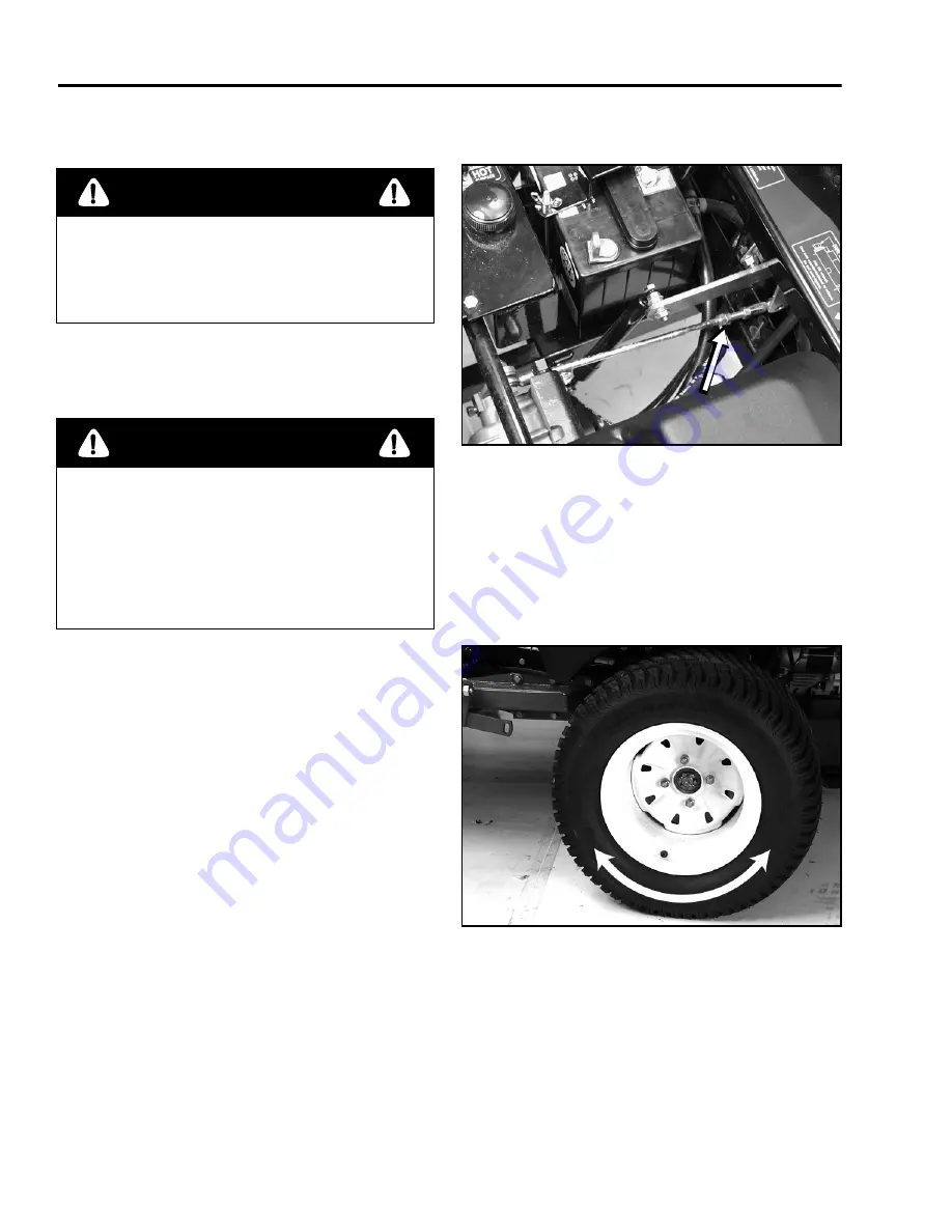
4.

Loosen locknut at ball joint on pump control rod 
(Figure 65).

Figure 65

1023-015

5.

Start engine, open throttle 1/2 way and release 
parking brake. 

Note: 

 The front nut of each rod has left-hand threads.

6.

Adjust pump rod length by rotating double nuts on 
rod, in the appropriate direction, until wheel is still 
or slightly creeps in reverse (Figure 66).

Figure 66

1227-005

7.

Move motion control lever forward and reverse, 
then back to neutral. Wheel must stop turning or 
slightly creep in reverse.

Note: 

 Motion control lever must be in neutral while

making any adjustments.

            DANGER

Mechanical or hydraulic jacks may fail to 
support machine and cause a serious injury.

• Use jack stand when supporting machine.
• Do not use hydraulic jacks.

           WARNING

Engine must be running so motion control 
adjustment can be performed. Contact with 
moving parts or hot surfaces may cause 
personal injury. 

Keep hands, feet, face, clothing and other body 
parts away from rotating parts, muffler and other 
hot surfaces.

Summary of Contents for 74161

Page 1: ...E AIR CLEANER CLEANING THE PRIMARY FILTER INSTALLING THE FILTERS SERVICING THE AIR CLEANER LIQUID COOLED MODELS REMOVING THE PAPER ELEMENT CLEANING THE PAPER ELEMENTS INSTALLING THE PAPER ELEMENTS CLEANING THE ENGINE FINS SERVICING THE COOLING SYSTEM CHECKING THE RADIATOR COOLANT CLEANING THE COOLING SYSTEM CHANGING THE ENGINE COOLANT INSPECTING THE COOLING SYSTEM SERVICING THE FUEL FILTER REPLACI...

Page 2: ... CHASSIS MOTION CONTROL LINKAGE REMOVE AND REPLACE ADJUSTING THE HANDLE NEUTRAL REPLACING THE PARKING BRAKE AND LINKAGE ADJUSTING THE PARKING BRAKE DESCRIPTION FUEL SYSTEM FUEL TANK REMOVE AND REPLACE REPLACE FRONT WHEEL BEARINGS FRONT CASTER BEARINGS REMOVE REPLACE MOWER DECKS REPLACING THE PTO DRIVE BELT MOWER DECK REMOVAL SPINDLE REPAIR ASSEMBLY DECK MOUNTING TYPICAL LEVELING THE MOWER CHECKING...

Page 3: ...G SWITCH PTO CLUTCH PURPOSE HOW IT WORKS TESTING BRAKE SWITCH PURPOSE HOW IT WORKS TESTING INTERLOCK MODULE PURPOSE HOW IT WORKS TESTING HOURMETER PURPOSE HOW IT WORKS TESTING MOTION CONTROL SWITCH PURPOSE HOW IT WORKS TESTING KEY SWITCH PURPOSE HOW IT WORKS TESTING SEAT SWITCH PURPOSE HOW IT WORKS TESTING MERCURY SWITCH PURPOSE HOW IT WORKS TESTING 20 AMP FUSE PURPOSE TESTING WIRING HARNESS TYPIC...

Page 4: ...Mid Mount Z Service Manual ...

Page 5: ...ase refer to the LCB Electrical Troubleshooting CD PN 492 4757 For information specific to the engines used on these products refer to the appropriate engine manufacturer s service and repair instructions We hope you find this manual a valuable addition to your service shop If you have any questions or comments regarding this manual please contact us at the following address The Toro Company Lands...

Page 6: ...the Filters 2 3 Installing the Filters 2 4 Servicing Models Equipped With the Heavy Duty Air Cleaner 2 4 Using the Filter Minder 2 4 Removing the Air Cleaner 2 5 Cleaning the Primary Filter 2 5 Installing the Filters 2 5 Servicing the Air Cleaner Liquid Cooled Models 2 5 Removing the Paper Element 2 5 Cleaning the Paper Elements 2 6 Installing the Paper Elements 2 6 Cleaning the Engine Fins 2 6 Se...

Page 7: ...e to Add Light Oil or Spray Lubrication 2 11 Greasing the Bearings 2 11 ENGINE External Alternator Remove Replace 3 1 Engine Remove Replace Air Cooled 3 2 Engine Remove Replace Liquid Cooled 3 3 Radiator Remove Replace Liquid Cooled Mowers 3 8 Models Equipped With Electronic Fuel Injection EFI 3 11 HYDRAULIC SYSTEMS Hydraulic System Typical 4 1 Description 4 2 General Hydraulic Assembly Guidelines...

Page 8: ...eplace 5 14 MOWER DECKS Replacing the PTO Drive Belt 6 1 Mower Deck Removal 6 3 Spindle Repair 6 4 Assembly 6 6 Deck Mounting Typical 6 9 Leveling the Mower 6 10 Checking for Bent Blades 6 11 Adjusting the Compression Spring 6 12 Spindle Assemblies Typical 6 13 ELECTRICAL SYSTEMS Electrical Schematics 7 1 Alternator Kohler 7 20 Purpose 7 20 How It Works 7 20 Testing 7 20 Regulator Rectifior 7 21 P...

Page 9: ...Purpose 7 26 How It Works 7 26 Testing 7 26 Brake Switch 7 27 Purpose 7 27 How It Works 7 27 Testing 7 27 Interlock Module 7 28 Purpose 7 28 How It Works 7 28 Testing 7 28 Hourmeter 7 29 Purpose 7 29 How It Works 7 29 Testing 7 29 Motion Control Switch 7 30 Purpose 7 30 How It Works 7 30 Testing 7 30 Key Switch 7 31 Purpose 7 31 How It Works 7 31 Testing 7 31 Seat Switch 7 32 Purpose 7 32 How It W...

Page 10: ... Mount Z Service Manual v TABLE OF CONTENTS ELECTRICAL SYSTEMS cont d Mercury Switch 7 33 Purpose 7 33 How It Works 7 33 Testing 7 33 20 Amp Fuse 7 34 Purpose 7 34 Testing 7 34 Wiring Harness Typical 7 35 ...

Page 11: ...vi Mid Mount Z Service Manual THIS PAGE INTENTIONALLY LEFT BLANK ...

Page 12: ...Cooled 74201 Kohler 25 2 1 Qts 3600 100 1500 Air Cooled 74202 Kohler 23 2 1 Qts 3600 100 1500 Air Cooled 74203 Kohler 25 2 1 Qts 3600 100 1500 Air Cooled 74204 Kohler 25 2 1 Qts 3600 100 1500 Air Cooled 74205 Kohler 25 2 1 Qts 3600 100 1500 Air Cooled 74209 Kohler 23 2 1 Qts 3600 100 1500 Air Cooled 74211 Kawasaki 22 2 1 Qts 3600 100 1500 Liquid Cooled 74212 Kawasaki 22 2 1 Qts 3600 100 1500 Liqui...

Page 13: ...th Width Height Weight lb Tires Tire Pressure Rear Front Rear Front 74228 50 79 8 66 44 5 1045 23 x 9 5 12 13 x 6 50 6 13 PSI 13 PSI 74225 53 81 5 74 44 5 1105 24 x 12 00 12 13 x 6 50 6 13 PSI 13 PSI 74226 53 81 5 74 44 5 1105 24 x 12 00 12 13 x 6 50 6 13 PSI 13 PSI 74227 55 25 84 5 85 44 5 1170 24 x 12 00 12 13 x 6 50 6 13 PSI 13 PSI Z280 Series Model Wheel Base Length Width Height Weight lb Tire...

Page 14: ...ro Gear BDP10A 2 Ross MB15 Torquemotors Mobil 1 15W20 Synthetic 2 1 Qts Z280 Series 2 Hydro Gear BDP10A 2 Ross MB15 Torquemotors Mobil 1 15W20 Synthetic 2 1 Qts Hydraulic Hoses Fittings Item Torque Fitting to hydraulic oil tank 50 70 ft lbs Fittings to hydraulic pumps 50 70 ft lbs Hoses to pump fittings 34 41 ft lbs Straight fittings to wheel motors 72 82 ft lbs Item Torque Wheel lug nuts 45 55 ft...

Page 15: ...1 4 Mid Mount Z Service Manual THIS PAGE INTENTIONALLY LEFT BLANK ...

Page 16: ...50 Hours Belts check for wear cracks Tires check pressure Every 100 Hours Engine Oil change1 Hydraulic lines check Engine Cooling System clean1 Every 200 Hours Oil Filter change 200 hours or every other oil change 1 Hydraulic filter change Spark Plug s check Fuel Filter replace Replace or clean primary air cleaner filter1 Every 500 Hours or at Storage Wheel Hub Slotted Nut adjustment Castor Pivot ...

Page 17: ...nutes This warms the oil so it drains better 2 Park the machine so that the drain side is slightly lower than the opposite side to assure the oil drains completely Disengage the power take off PTO set the parking brake and turn the ignition key to off Remove the key 3 Place a pan below the oil drain Rotate oil drain valve to allow oil to drain Figure 2 Figure 2 m 4386 4 When oil has drained comple...

Page 18: ... body Figure 3 Avoid knocking the filter into the side of the body Do not remove the safety filter unless you intend to replace it as well 5 Inspect the primary filter for damage by looking into the filter while shining a bright light on the outside of the filter Holes in the filter will appear as bright spots If the filter is damaged discard it Never attempt to clean the safety filter If the safe...

Page 19: ...lter Replace after every 600 operating hours Note Service the air cleaner more frequently if operating conditions are extremely dusty or sandy Using the Filter Minder This machine contains an air cleaner Filter Minder gauge Filter Minder Check this daily The plunger inside the gauge canister will change to red when the air cleaner element becomes dirty and restricted When it changes red air cleane...

Page 20: ...d keep the hose at least 2 inches from the filter Replace air filters if they are damaged or cannot be cleaned Installing the Filters To prevent engine damage always operate the engine with both air filters and cover installed 1 If installing new filters check each filter for shipping damage Do not use a damaged filter 2 If the safety filter is being replaced carefully slide it into the filter bod...

Page 21: ... m 4383 Installing the Paper Elements To prevent engine damage always operate the engine with the paper air cleaner installed 1 Carefully slide the element into the compartment Figure 6 2 Place the air cleaner cover into the compartment and latch the retaining clips Figure 6 Cleaning the Engine Fins Every 100 hours clean engine cylinder and cylinder head cooling fins Also clean around carburetor g...

Page 22: ... engine and set the parking brake Before starting the engine clean grass from the pump drive belt compartment Check more often in dry conditions 2 Tilt the seat up and raise the rubber flap above the drive belt compartment 3 Remove debris from the drive belt compartment and hydraulic pumps Danger Discharge of hot pressurized coolant or touching hot radiator and surrounding parts can cause severe b...

Page 23: ...block Figure 10 NOTE The drain plug is black in color and is located near the oil filter Figure 10 5 Install all drain plugs the radiator hose and tighten the drain cock Figure 9 m 4379 Figure 10 m 5030 Danger Discharge of hot pressurized coolant or touching hot radiator and surrounding parts can cause severe burns Do not remove the radiator cap when the engine is hot Always allow the engine to co...

Page 24: ...e 13 Check for any leaks in the cooling system 14 Close the engine cover and tilt the seat back Check the coolant level after the first 8 hours of changing the coolant Figure 11 m 5031 2 Inspecting the Cooling System Inspect the radiator and the hoses initially and after the first 8 operating hours Inspect the radiator and the hoses every 200 hours Check the hoses and radiator for cracks dents and...

Page 25: ...ure 13 Now clean around the spark plug s to prevent dirt from falling into the engine and potentially causing damage Figure 13 m 3218 3 Remove the spark plug s and metal washer Checking the Spark Plug 1 Look at the center of the spark plug s Figure 14 If you see light brown or gray on the insulator the engine is operating properly A black coating on the insulator usually means the air cleaner is d...

Page 26: ...e zerk into hole 2 Pump grease into zerk until it oozes out around top bearing 3 Remove grease zerk in hole Reinstall hex plug and cap Where to Add Grease Lubricate the grease fittings as shown on the Check Service Reference Aid decal Figure 15 Where to Add Light Oil or Spray Lubrication Lubricate the machine in the following areas with spray type lubricant or light oil Lubricate every 160 hours S...

Page 27: ...2 12 Mid Mount Z Service Manual THIS PAGE INTENTIONALLY LEFT BLANK ...

Page 28: ...to the side Figure 17 0508 002 3 Remove the alternator adjustment bolt and pivot bolt Figure 18 0508 003 4 Remove the alternator belt and rotate the alternator to gain access to the wiring Figure 19 0508 004 5 Remove the alternator output wire ground wire and exciter wire 6 Inspect the alternator belt for wear cracking or other damage 7 Reverse procedure to reinstall A Ground Wire B Exciter Wire C...

Page 29: ...ug and main wiring harness connector Figure 21 6 Release the tension from the drive belt by raising the lever against the spring tension and remove the belt from the PTO pulley Figure 22 Figure 22 1101 011 7 Remove the clamps securing the choke and throttle cables Then remove the Z bends from the choke and throttle levers Figure 23 Figure 23 1023 005 8 Place the fuel tank selector lever in the off...

Page 30: ... machine and rotate it slightly counterclockwise until the hydraulic pump belt drive pulley clears the chassis Then lift the engine from the chassis Engine Remove Replace Liquid Cooled 1 Disconnect the negative battery cable Figure 25 0507 001 2 Remove the pins from the radiator cover and lift off the cover Figure 26 0507 002 3 Remove the radiator cap and open the drain petcock to drain the coolan...

Page 31: ... water pump and thermostat housing and remove the hoses from the fittings 6 Unplug the electrical connections from the temperature sender and fan motor Figure 29 0507 005 7 Remove the bolts securing the overflow bottle to the engine guard Figure 30 0507 006 8 Remove the 7 bolts securing the radiator support to the engine guard 9 Carefully lift the radiator assembly from the unit Figure 31 0507 007...

Page 32: ...retor Figure 32 0507 008 11 Remove the 2 bolts securing the air cleaner to the frame and remove the air cleaner Figure 33 0507 009 12 Remove the 6 bolts securing the rear bumper to the engine guard Figure 34 0507 010 13 Remove the bolts securing the engine guard bars to the brackets Figure 35 0507 011 ...

Page 33: ...wer feed from the starter Then separate the engine harness connector and electric clutch connector Then remove the engine ground wires Figure 37 0507 013 16 Remove the alternator output and ground wires Figure 38 0507 014 17 Lift the lever on the deck belt tension pulley and remove the belt Figure 39 0507 015 A Engine Harness B Positive Battery Cable C Engine Ground D Clutch Connector A B C D ...

Page 34: ...1 0507 017 20 Make sure the fuel selector is in the off position Then remove the fuel line from the carburetor CAUTION Gasoline is extremely flammable Drain into a suitable container and keep away from any source of combustion Figure 42 0507 018 21 Remove the bolts securing the engine base to the chassis Then carefully slide the engine back making sure that the fan clears the fan shroud Figure 43 ...

Page 35: ...lift off the cover Figure 45 0507 002 3 Remove the radiator cap and open the drain petcock to drain the coolant into a suitable container Figure 46 0507 003 4 To drain the block remove the drain bolts NOTE Apply sealant to the bolt threads during reassembly Figure 47 0507 004 5 Loosen the radiator hose clamps at the water pump and thermostat housing and remove the hoses from the fittings ...

Page 36: ...fan motor Figure 48 0507 005 7 Remove the overflow hose from the radiator Figure 49 0507 020 8 Remove the 7 bolts securing the radiator support to the engine guard 9 Carefully lift the radiator assembly from the unit Figure 50 0507 007 10 Remove the hose clamps from the radiator fittings Figure 51 0507 021 ...

Page 37: ...12 Carefully work the hoses free from the radiator fittings Figure 53 0507 010 13 Turn the radiator over Remove the 6 bolts securing the upper radiator support to the radiator and remove the support Figure 54 0507 024 14 If it is necessary to remove the electric fan assembly remove the 4 nuts and bolts securing it to the lower radiator support Figure 55 0507 025 ...

Page 38: ...are the locations of components which are EFI related but mounted to the unit s chassis 1 The fuel pressure regulator is mounted to the right side of the frame behind the rear tire Figure 56 0507 026 2 The electronic control unit ECU is located under the engine at the rear of the unit Figure 57 0507 027 3 The diagnostic plug is installed on the right side of the machine near the starter Figure 58 ...

Page 39: ...3 12 Mid Mount Z Service Manual THIS PAGE INTENTIONALLY LEFT BLANK ...

Page 40: ...wer Pressure Hose 9 1 Tank Cap Gasket 33 1 Bearing Arm ASM 10 4 Connector Fitting 34 2 HH Screw 10 4 90 Deg Fitting 35 1 HH Screw 11 2 Wheel Motor 36 1 HH Screw 12 1 Idler Pivot Bushing 37 1 HH Screw 13 1 Extension Spring 38 4 HH Screw 14 1 Hose Tee Fitting 39 2 Screw 15 1 Hose Tee Fitting 40 2 Screw 16 3 Hose Clamp 41 2 Set Screw 17 5 Hose Clamp 43 1 Flat Washer 18 1 Elbow Fitting 44 1 Flat Washe...

Page 41: ...til just prior to assembly Make sure that no paint flakes fall into the open port Do not remove plastic plugs with a sharp knife 3 Ensure that the fittings are clean free from nicks and corrosion The insides of all hoses and lines must be clean 4 Always apply clean oil to all O rings prior to assembly 5 Once a hose or steel line is started it is important to continue to tighten until finger tight ...

Page 42: ... the location of the wheel motor supply hoses as to which fitting they go on the wheel motor Remove the hose fittings to the pump and install caps to keep dirt out Figure 63 1227 002 5 Using a suitable pry bar release the spring tension on the idler pulley and remove the drive belt from the pump pulley Figure 64 Figure 64 1023 012 6 Remove the 2 nuts and bolts securing the pump to the chassis and ...

Page 43: ... nut of each rod has left hand threads 6 Adjust pump rod length by rotating double nuts on rod in the appropriate direction until wheel is still or slightly creeps in reverse Figure 66 Figure 66 1227 005 7 Move motion control lever forward and reverse then back to neutral Wheel must stop turning or slightly creep in reverse Note Motion control lever must be in neutral while making any adjustments ...

Page 44: ...sen the nut B Figure 67 securing the hub to the output shaft Release the parking brake 5 Remove the 3 bolts securing the brake band C Figure 67 to the brake actuator Then remove the brake band from the hub 6 Install the special puller on to the hub and tighten the forcing screw until the hub is free of the wheel motor output shaft Figure 68 Figure 68 1227 003 7 Clean any dirt and debris away from ...

Page 45: ...Service Manual 8 Remove the front two wheel motor mounting bolts and swing the brake linkage out of the way Figure 70 9 Remove the rear two wheel motor mounting bolts and then remove the wheel motor from the chassis Figure 70 Figure 70 ...

Page 46: ...al switch Figure 72 Figure 72 1023 018 3 Remove the motion control handle 4 Remove the pin from the clevis on the control lever centering rod Figure 73 5 Remove the control link from the bell crank Figure 73 Figure 73 1023 013 6 Disconnect the steering dampening cylinder from the bell crank 7 Remove the bolts securing the bell crank inside bearing Figure 73 8 Remove the bolt securing the bell cran...

Page 47: ...low pivot shaft contacts the end of the slot just beginning to put pressure on spring Figure 76 Figure 76 1227 007 3 Check where lever is relative to notch in console should be centered allowing lever to pivot outward to the neutral lock position Figure 76 4 If adjustment is needed loosen the nut against the yoke 5 Apply slight rearward pressure on the motion control lever turn the head of the adj...

Page 48: ...ylon Flanged Bushing 24 2 Screw 6 2 Neutral Return Bolt 25 6 Lock Nut 7 2 Neutral Return Spring 26 10 Hex Nut 8 4 HH Screw 27 2 Nut 11 1 RH Lever Grip ASM 28 2 Nut 12 2 Pump Control Arm WLD 29 2 Flat Washer 13 1 LH Motion Control 30 4 Flat Washer 14 1 RH Motion Control 32 2 Cotter Pin 15 2 Pump Lever Linkage 33 2 Clevis Pin 16 4 Side Flange Bearing 34 16 HF Nut 17 2 LH Thread Ball Joint 35 8 Flang...

Page 49: ...s securing the brake band to the brake pivot Figure 77 Figure 77 1030 001 5 Inspect the brake bands for wear damage or overheating Figure 78 Figure 78 1030 002 6 Using the special puller remove the brake hub from the wheel motor Figure 79 Figure 79 1227 003 7 Remove the 3 clevis pins from the brake rods and remove the brake rods from the brake shaft Figure 80 The third pin is on the opposite end o...

Page 50: ...he brake shaft first remove the hydraulic fluid reservoir which is held in place by 2 cap screws and nuts Figure 82 Figure 82 1030 006 10 Then remove the brake shaft bearing bolts at either end of the shaft Figure 83 Figure 83 1030 009 11 Then lift the brake shaft out of the chassis 12 To remove the brake lever first remove the control panel at the console Figure 84 Figure 84 1030 008 ...

Page 51: ...unt Z Service Manual 13 To remove the brake handle remove the cotter pin from the brake handle pivot shaft Figure 85 Figure 85 1030 003 14 Then pull the brake handle out of the brass bearing Figure 86 Figure 86 1030 007 ...

Page 52: ...ke Lever Grip ASM 21 2 Grease Fitting 5 1 Brake Shaft 22 8 Square Nut 6 2 Brake Bracket 23 8 HH Nut 7 2 Spacer Washer 24 4 Flange Nut 9 2 Brake Bank 25 8 Lock Washer 6 2 Brake Bracket 26 4 Flat Washer 10 4 Short Wheel Spacer 27 7 Cotter Pin 11 4 Long Wheel Spacer 28 2 Cotter Pin 12 2 Side Flange Bearing 29 6 HH Screw 13 4 Brake Linkage Yoke 30 6 Spacer 14 2 Trunion Pin 31 2 Brake Band Retainer 15 ...

Page 53: ...the nut until the correct measurement is obtained Tighten the two nuts together and repeat on opposite side of unit 4 Turn nuts clockwise to shorten spring length and turn counterclockwise to lengthen the spring 5 Engage parking brake A Measure the distance between the trunnion roller and the collar on brake rod Measurement should be 3 16 1 4 in 5 7mm Figure 88 Figure 88 1227 010 6 If adjustment i...

Page 54: ...PTO switch and temperature gauge on liquid cooled models Ref No Qty Description Ref No Qty Description 1 9 Fuel Line Clamp 16 2 HH Screw 2 1 Control Panel 17 6 Lock Nut 3 1 Hose Clamp 18 2 Flat Washer 5 2 Gas Cap ASM 19 2 Lock Washer 6 2 Fuel Valve Bushing 20 8 Flat Washer 8 3 Fuel Hose 21 1 Control Panel Decal 8 2 Fuel Hose 22 1 Control Panel Shield 9 6 Stud 23 4 Screw 10 1 LH Fuel Tank 24 4 Spri...

Page 55: ...from the fuel filter Place the fuel line into a suitable container Figure 89 Use the fuel valve to select the tank to be removed Figure 90 Figure 89 Figure 90 1030 031 3 If the left tank is to be removed remove the electrical control panel from the tank Figure 91 Figure 91 1030 030 4 Remove the tire Then remove the 2 nuts springs and washers securing the center of the fuel tank to the frame Figure...

Page 56: ...nk to the frame Figure 94 Figure 94 1030 034 7 Lift the tank and make sure it is completely drained of fuel 8 Remove the fuel line from the fitting at the front of the tank Figure 95 Figure 95 1030 032 Reverse these steps to reinstall NOTE When replacing the nut spring and washer assemblies only tighten the nut so that approximately 1 8 3 2mm of threads are exposed Figure 96 Figure 96 1030 028 1 8...

Page 57: ...els are off the ground 2 Remove the through bolt holding the wheel to the caster assembly Figure 97 Figure 97 1030 021 3 Remove the sleeve that passes through the wheel bearings Figure 98 Figure 98 1030 023 4 Remove the 2 wheel spacers Figure 99 Figure 99 1030 024 5 Remove the bearing seal Figure 100 Figure 100 1030 022 ...

Page 58: ...7 Drive the bearing race out from the opposite side of the wheel using a long drift Figure 102 Figure 102 1030 018 8 Clean the bearing and bearing race and inspect for signs of pitting or other damage Figure 103 Figure 103 1030 017 9 Press a new race into the wheel hub Figure 104 Figure 104 1030 019 ...

Page 59: ... to reassemble Front Caster Bearings Remove Replace 1 Remove the dust cap at the top of the caster assembly Figure 107 Figure 107 1030 011 2 Hold the caster assembly stationary and loosen the bearing adjustment nut Figure 108 Figure 108 1030 010 3 Remove the bearing adjuster nut while holding the caster assembly 4 Remove the upper caster bearing 5 Pry the lower bearing seal out of the housing and ...

Page 60: ...her damage Figure 109 Figure 109 1030 017 7 Pack the bearings with grease and reinstall in the housing Press in a new seal 8 Reassemble the caster into the bearings Figure 110 Figure 110 1030 012 9 Tighten the bearing adjustment nut until there is a slight drag felt in the bearings 10 Replace the dust cap ...

Page 61: ...e Manual Wheel and Caster Assembly Ref No Qty Description 1 2 Grease Cap 2 2 Lock Nut 3 6 Belleville Washer 4 4 Tapered Roller Bearing 5 4 Cup Bearing 7 2 Grease Seal 8 2 Caster 11 2 Caster Wheel Assembly 21 2 HH Screw 22 2 Lock Nut ...

Page 62: ...erminal from wire harness Figure 111 Figure 111 1228 004 3 Remove PTO drive belt from pulley and front idler pulley assembly Remove the PTO drive belt Figure 112 Figure 112 m 4312 4 Place new drive belt over clutch around rear idler pulley installed into rear idler arm assembly installed into front idler pulley assembly and onto top center pulley Figure 113 Check the amount of twist in belt betwee...

Page 63: ...r on right support plate and move up or down in adjustment slot To relieve belt tension lift up on spring loaded idler Figure 115 1228 002 8 Check belt tension again The center bolt of spring loaded idler must be between the two alignment holes in left support plate Figure 114 Adjust if necessary and tighten all hardware securely 9 If the fixed idler contacts the end of the adjustment slot and mor...

Page 64: ...he deck struts to the mower frame Figure 119 Figure 119 1101 010 5 Remove the struts from the deck by first removing the nut and bolt that holds the pin to the deck Slide the pin out of the strut to release it from the deck Figure 120 Figure 120 1101 009 6 The first step in deck removal is to place the deck in the lowest position 7 The second step is to lock the deck height lever in position by pl...

Page 65: ...nd remove the blade 9 Remove the spindle shaft from the spindle housing It may need to be pressed out of the housing Note The lower bearing spacer will remain on the spindle shaft 10 Inspect the spindle shaft for the following Figure 122 A Elongated grease axis hole A Normally this hole is perfectly round if it is deformed it is directly a result of impact B Damaged splines B If the splines are tw...

Page 66: ...l operating position Failure to do this may cause premature bearing failure when reassembled Inspect the bearings as follows Figure 124 A Look for the presence of grease particularly in the upper bearing Dry or cooked grease indicates a lack of maintenance B Look for dirt in the grease Dirt in the grease indicates a bad seal or a worn lower bearing spacer If the unit was recently rebuilt look for ...

Page 67: ...damage or wear E Pulley assembly If the shaft shows signs of wear inspect the pulley for excessive wear in the splines If excessive wear is found replace the pulley Excessive wear of the splines will show up as a sharp edge on the splines NOTE New bearings are only available in matched sets The matched set is necessary because the bearing endplay is not adjustable The small C shaped spacer is mach...

Page 68: ...e both seal lips with grease and insert the bearing spacer into the lower seal By inserting the spacer individually and not with the shaft you will prevent possible damage to the lower seal 24 Bolt the assembly back into the deck shell 25 Install the spindle shaft Note the shaft will slide out if not supported 26 Slide the pulley down onto the shaft and secure with the washer and nut Be certain to...

Page 69: ...ley D Spindle Housing E Bearing Cup F Small Spacer G Snap Ring H Bearing Cone I Bearing Spacer J Grease Axis Hole K Blade Bolt L Spring Washer M Blade N Spindle Shaft O Seal P Bearing Cup Q Machined C Spacer R Large Spacer S Bearing Cone T Seal U Hardened Washer ...

Page 70: ... Mounting Typical Ref No Qty Description 1 16 HF Nut 2 8 HH Cap Screw 3 4 Deck Lift Chain 4 4 Grease Fitting 5 2 Hex Nut 6 2 Lock Washer 7 2 HH Screw 8 2 Spherical Balljoint 9 2 Hex Nut 10 2 Deck Strut 11 2 Deck Strut Pin 12 2 HH Screw 13 2 Lock Nut ...

Page 71: ...n front of each spring Figure 128 Figure 128 1101 008 02 5 Place two 1 1 2 in 38mm thick blocks under rear left and right lower edge of mower Place one 2 1 4 in 57mm block under front center lower edge of mower Figure 129 Figure 129 1101 007 Lower mower to the 2 in 51mm height of cut position 6 Loosen the four top chain bolts in slots Check the length of the rod swivel assemblies Distance from out...

Page 72: ...d with the same procedure as Checking for Bent Blades on page 6 11 12 Install anti scalp rollers for proper height of cut and tighten securely Checking for Bent Blades 1 Rotate the blades until the ends face forward and backward Figure 131 Measure from a level surface to the cutting edge of the blades Figure 132 Note this dimension Figure 131 m 1078 Figure 132 m 2539 2 Rotate the opposite ends of ...

Page 73: ...the transport position Figure 133 Figure 133 1228 005 2 Springs are compressed so the distance between the two large washers should be 11 in 279mm Figure 134 Figure 134 Adjust by turning nut in front of each spring Figure 134 Clockwise will shorten spring counterclockwise will lengthen spring 11 in 279mm ...

Page 74: ...Cap Screw 17 3 Spring Washer 4 1 Torsion Spring 18 3 Blade 5 1 Belt Guide 19 1 Flat Washer 7 1 ASM Deflector 20 18 HF Nut 8 1 Lock Nut 21 2 Outer Spindle ASM 9 1 HH Screw 22 1 Middle Spindle ASM 10 1 Flat Washer 23 17 Carr Screw 11 8 Flange Lock Nut 26 1 Deflector Mounting 13 8 HWH Screw 14 4 Slotted Clamp 15 2 Blade Bolt ...

Page 75: ...6 14 Mid Mount Z Service Manual THIS PAGE INTENTIONALLY LEFT BLANK ...

Page 76: ...Mid Mount Z Service Manual 7 1 ELECTRICAL SYSTEMS ...

Page 77: ...ELECTRICAL SYSTEMS 7 2 Mid Mount Z Service Manual Models 74170 74200 74171 74201 74172 74202 74173 74203 74174 74204 74175 74205 74209 Start Circuit ...

Page 78: ...Mid Mount Z Service Manual 7 3 ELECTRICAL SYSTEMS Models 74170 74200 74171 74201 74172 74202 74173 74203 74174 74204 74175 74205 74209 Run Circuit ...

Page 79: ...ELECTRICAL SYSTEMS 7 4 Mid Mount Z Service Manual ...

Page 80: ...Mid Mount Z Service Manual 7 5 ELECTRICAL SYSTEMS Models 74211 74212 Start Circuit ...

Page 81: ...ELECTRICAL SYSTEMS 7 6 Mid Mount Z Service Manual Models 74211 74212 Run Circuit ...

Page 82: ...Mid Mount Z Service Manual 7 7 ELECTRICAL SYSTEMS ...

Page 83: ...ELECTRICAL SYSTEMS 7 8 Mid Mount Z Service Manual Models 74218 74219 Start Circuit ...

Page 84: ...Mid Mount Z Service Manual 7 9 ELECTRICAL SYSTEMS Models 74218 74219 Run Circuit ...

Page 85: ...ELECTRICAL SYSTEMS 7 10 Mid Mount Z Service Manual ...

Page 86: ...Mid Mount Z Service Manual 7 11 ELECTRICAL SYSTEMS ...

Page 87: ...ELECTRICAL SYSTEMS 7 12 Mid Mount Z Service Manual ...

Page 88: ...Mid Mount Z Service Manual 7 13 ELECTRICAL SYSTEMS ...

Page 89: ...ELECTRICAL SYSTEMS 7 14 Mid Mount Z Service Manual ...

Page 90: ...Mid Mount Z Service Manual 7 15 ELECTRICAL SYSTEMS ...

Page 91: ...ELECTRICAL SYSTEMS 7 16 Mid Mount Z Service Manual ...

Page 92: ...Mid Mount Z Service Manual 7 17 ELECTRICAL SYSTEMS ...

Page 93: ...ELECTRICAL SYSTEMS 7 18 Mid Mount Z Service Manual ...

Page 94: ...Mid Mount Z Service Manual 7 19 ELECTRICAL SYSTEMS ...

Page 95: ...m The current produced is alternating current since no diode or rectifier is internal to the stator With regulator rectifier disconnected Testing 1 Remove the connector from the regulator rectifier Measure the voltage across the two A C leads on the alternator side of the connector with the engine running at 3600 rpm If voltage is less than 28 volts proceed to the next step Otherwise stator is OK ...

Page 96: ...nnected to the battery to function Once the voltage level of the battery has surpassed 14 7 volts the voltage regulator shuts off all current and no charging takes place When the voltage again drops below the specified level the voltage regulator turns the current back on at the rated amperage of the alternator Testing 1 Connect a DC voltmeter across the battery 2 Run the engine at 3600 RPM V If t...

Page 97: ...not in contact with the clutch plate and is pressed against the brake material opposite the clutch When power is applied the friction plate is drawn toward the clutch plate and the two rotate as one Testing 1 Disconnect the PTO clutch from the harness 2 Connect a charged 12 volt battery to the clutch polarity makes no difference You should hear a click the clutch should engage If not check the wir...

Page 98: ...ch plug 4 Use the flats on the washer below the clutch retaining bolt to hold the crankshaft stationary remove the clutch retaining bolt Figure 136 Figure 136 1023 001 5 Rotate the clutch assembly until the anchor will clear the lower clutch guard Then slide the clutch assembly off of the crankshaft while holding the 2 clutch halves together Figure 137 Figure 137 1023 003 NOTE On reassembly torque...

Page 99: ... is applied to the coil it becomes an electromagnet This quickly pulls the steel bar toward the contacts and closes the switch When power is removed from the coil the spring loaded bar returns to its normally open position Note The solenoid closes and opens the switch very quickly This minimizes the arcing that can damage other type switches Testing 1 Disconnect the solenoid from the wiring harnes...

Page 100: ...the commutator The armature rotates COMMUTATOR The commutator is the connection point between the brushes and the coils in the armature The sections are divided such that only one armature coil is on at a time This sets the armature to rotating because the electromagnetic field in the field coil will oppose the one in the armature BRUSHES Supply power to the commutator Testing With the starter ass...

Page 101: ...ipped by a single lever One of the SPDT switches is connected to the electric PTO clutch When in the off position this side of the switch is open The other half of the switch is used by the safety interlock system When the clutch is off this side of the switch is closed This allows current to keep the kill relay energized so that the mag is not grounded out Testing 1 Disconnect the switch from the...

Page 102: ...onnected to the light blue wires are part of the interlock circuit and must be closed to provide ground for the starter solenoid The contacts connected to the green wires must be open brake released when the control levers are in the operating position in or a ground signal is provided to the ignition kill terminal to shut down the engine Testing Connect an ohmmeter across each pair of contacts in...

Page 103: ...otion control switches This circuit is closed when the blade switch is off and the control levers are in the out position allowing the engine to run with the operator out of the seat When the unit is in operation blade switch on and control levers in the brown wire is connected to ground through the seat switch If ground is removed from the brown wire the module waits a half second and then shuts ...

Page 104: ...switch is in the ON position power is supplied to the terminal of the hourmeter from the A terminal orange wire of the ignition switch When the engine is running oil pressure closes the oil pressure switch supplying a ground to the terminal of the hourmeter Testing Connect B to the terminal and ground to the terminal the hourmeter should run Hourmeter Back Hourmeter ...

Page 105: ...hese contacts are open preventing the starter from cranking The second pair of contacts connected to the green wires prevent operation of the unit with the parking brake applied Moving the control levers in closes these contacts sending a ground signal to the brake switch If the brake is applied the ground signal is sent to the engine kill terminal shutting down the engine Testing 1 With the switc...

Page 106: ... OFF RUN and START The START position is spring loaded so the switch returns to the RUN position when the key is released Testing 1 Disconnect the switch from the wiring harness 2 Verify the conditions in the table 3 There should not be continuity between any of the switch terminals and ground KEY SWITCH LOGIC Position Circuit Off E G On B A Start B A S Key Switch Start Battery Ground Accessory En...

Page 107: ...itch contacts are open when there is no operator on the seat When the operator is in position the linkage allows the switch plunger to extend closing the contacts Testing With the seat switch removed from the unit connect an ohmmeter across the contacts When the plunger is extended the meter should show continuity When the plunger is pushed in the meter should show open circuit Seat Switch ...

Page 108: ...witch When the tilt angle of the unit is less than 60 the mercury connects the contacts in the switch When the tilt angle exceeds 60 the mercury flows away from the contacts causing the switch to open Testing 1 Connect an ohmmeter across the switch 2 When the switch is vertical the meter should show continuity 3 Tilt the switch 60 The meter should show open circuit Mercury Switch ...

Page 109: ...ng an open circuit Fuses are rated for specific currents amps Never connect a jumper wire across a fuse Never connect additional fuses in parallel Always use the proper fuse Always find and correct the reason for a blown fuse Testing A blade type fuse may be checked visually If the loop A is open the fuse is blown If in doubt the fuse may also be tested with an ohmmeter 20 Amp Fuse A ...

Page 110: ...1 Battery Insulator 23 1 Key Switch ASM 6 1 HH Screw 24 1 Hourmeter 7 2 Flat Washer 25 1 Delta Switch 8 2 HF Nut 26 3 Loom Clip 9 1 Seat Switch Spring 27 1 Wire Harness 10 1 Seat Spring Mount 28 2 Plastic Tie 11 6 HH Screw 29 1 Starter Wire 12 6 HF Nut 30 1 Solenoid Insulator 13 2 Ignition Key 31 2 Holddown Bolt 14 1 Normally Closed Switch 32 1 Tilt Switch 15 1 Seat Switch Plate 33 6 Lock Nut 16 1...

Page 111: ...7 36 Mid Mount Z Service Manual THIS PAGE INTENTIONALLY LEFT BLANK ...

Page 112: ......

Page 113: ...492 4758 ...

Reviews: