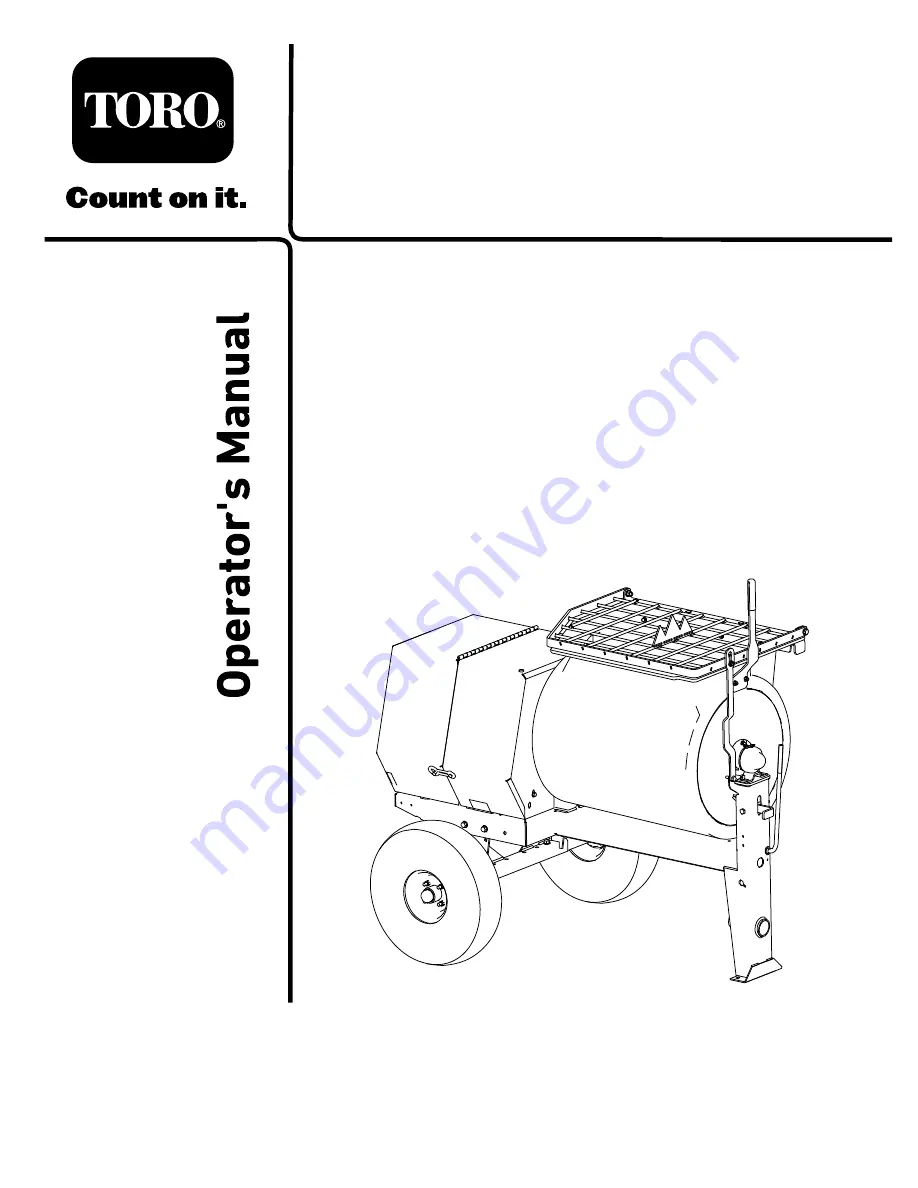
Toro 60217 Operator'S Manual Download Page 1

Form No. 3422-822 Rev A

MMX-658K-P, MMX-858K-P, and
MMX-858H-P Mortar Mixers

Model No. 60217—Serial No. 400000000 and Up

Model No. 60217C—Serial No. 400000000 and Up

Model No. 60221—Serial No. 400000000 and Up

Model No. 60221C—Serial No. 400000000 and Up

Model No. 60221HD—Serial No. 400000000 and Up

Register at www.Toro.com.
Original Instructions (EN)

*3422-822* A


Summary of Contents for 60217

Page 1: ... Model No 60217 Serial No 400000000 and Up Model No 60217C Serial No 400000000 and Up Model No 60221 Serial No 400000000 and Up Model No 60221C Serial No 400000000 and Up Model No 60221HD Serial No 400000000 and Up Register at www Toro com Original Instructions EN 3422 822 A ...

Page 2: ... SE West Building Washington DC 20590 You can also obtain other information about motor vehicle safety from http www safercar gov To contact Transport Canada you may call 1 800 333 0510 or 819 994 3328 go to http www tc gc ca roadsafety write to Road Safety and Motor Vehicle Regulation Directorate Transport Canada Tower C Place de Ville 330 Sparks Street Ottawa Ontario K1A 0N5 or email RoadSafety ...

Page 3: ...safety alert symbol Figure 2 which signals a hazard that may cause serious injury or death if you do not follow the recommended precautions g000502 Figure 2 Safety alert symbol This manual uses 2 words to highlight information Important calls attention to special mechanical information and Note emphasizes general information worthy of special attention 3 ...

Page 4: ...eparing the Machine for Maintenance 29 Disconnecting the Spark Plug Wire 29 Removing the Divider Plate 29 Installing the Divider Plate 29 Lubrication 30 Lubricating the Bearings Seals and Gears 30 Engine Maintenance 31 Servicing the Air Cleaner 31 Servicing the Engine Oil 32 Servicing the Spark Plug 34 Cleaning the Spark Arrester 35 Removing and Installing the Engine 36 Fuel System Maintenance 38 ...

Page 5: ...sure that everyone using this product knows how to use it and understands the warnings Become familiar with the safe operation of the equipment operator controls and safety signs All operators and mechanics should be trained The owner is responsible for training them Never let children or untrained people operate or service the equipment Local regulations may restrict the age of the operator The o...

Page 6: ...re tight and torqued properly Ensure that the machine is properly secured Fuel Safety Use extreme care in handling fuel It is flammable and its vapors are explosive Extinguish all cigarettes cigars pipes and other sources of ignition Use only an approved fuel container Do not remove the fuel cap or fill the fuel tank while the engine is running or hot Do not add or drain fuel in an enclosed space ...

Page 7: ...ntenance or storing the machine Disengage all power and operation controls Never lubricate service repair or adjust the machine with the engine running Keep equipment materials clear from the muffler and engine to prevent fires Clean up oil or fuel spills Never allow untrained personnel to service the machine Keep your hands feet and clothing away from moving parts If possible do not make adjustme...

Page 8: ...ng hazard of hand entanglement hazard of hand at the shaft keep your hands away from moving parts keep all guards and shields in place 5 Explosion hazard shut off the engine and keep away from flames when refueling 3 Entanglement hazard at paddles shut off the engine and wait for all moving parts to stop before performing maintenance decal125 8175 125 8175 1 Read the Operator s Manual for informat...

Page 9: ...e fuel with an alcohol content by volume under 10 only 3 Do not use fuel with an alcohol content greater than 10 by volume 2 Read the Operator s Manual for more information on fuel decal133 5619 133 5619 decal137 7483 137 7483 9 ...

Page 10: ...decal137 7491 137 7491 1 Read the Operator s Manual 10 ...

Page 11: ...tow pole kit 1 3 Connecting link included with the tow pole kit 2 Install the safety chain 4 No parts required Adjust the mixing paddles 1 Installing the Dump Handle Parts needed for this procedure 1 Dump handle 2 Carriage bolt 2 Nut Procedure 1 Cut the cable ties to remove the dump handle from the underside of the grate 2 Install the dump handle to the side of the drum using 2 carriage bolts inst...

Page 12: ...n the frame fitting Figure 4 3 Insert the bolt through the holes in the fitting and the pole Figure 4 4 Thread the nut onto the bolt and tighten them until they are tight against the frame fitting Figure 4 Note If the self locking nylon insert in the locknut wears with use replace the nut with a new Grade 5 or Grade 8 locknut 3 Installing the Safety Chain Parts needed for this procedure 1 Safety c...

Page 13: ...ner walls of the drum refer to Adjusting the Paddles page 47 Product Overview g232184 Figure 6 Right side 1 Rear cowl 7 Clutch lever 13 Chute 2 Front cowl 8 Drum latch 14 Axle 3 Grate 9 Front post 15 Cowl latch 4 Bag splitter 10 Tow pole 16 Wheel assembly 5 Dump handle 11 Safety chain keyhole 6 Grate lift arm 12 Drum 13 ...

Page 14: ...e paddles g019875 Figure 7 1 Clutch lever Drum Latch Use the drum latch to secure the drum to the mix position upright for mixing operations and when transporting the machine g019877 Figure 8 1 Drum latch Dump Handle Use the dump handle to rotate the drum to the dump position and to rotate the drum to the mix position upright g232185 Figure 9 1 Dump handle 14 ...

Page 15: ...Figure 12 and Figure 13 is located underneath the choke lever Move the lever for the fuel valve to the ON position before attempting to start the engine When you have finished mixing shut off the engine and move the fuel valve lever to the OFF position g018792 Figure 12 Model 60221HD shown 1 Fuel valve 3 Throttle lever 2 Choke lever g232321 Figure 13 Models 60217 C 60221 C shown 1 Fuel valve 2 Cho...

Page 16: ...position when mixing material Engine On Off Switch The On Off switch is located on the front of the engine Rotate it to the ON position to start and run the engine Rotate it to the OFF position to shut off the engine g021103 Figure 14 1 OFF position 2 ON position Recoil Start Handle To start the engine pull the recoil start handle Figure 10 and Figure 11 quickly to turn the engine over The engine ...

Page 17: ...ders avoid injury Know how to quickly shut down the machine in an emergency Use a hard hat hearing protection a shirt with long sleeves that are tight at the wrists tight fitting gloves without drawstrings or loose cuffs eye protection and a dust mask or respirator A mesh visor alone does not provide sufficient eye protection supplement with protective glasses CAUTION This machine produces sound l...

Page 18: ...ompatible with the electrical connector of the machine The machine uses a standard 4 pin flat plug If your tow vehicle has a different type of plug obtain an adapter from an automotive parts store Preparing the Machine for Towing 1 Shut off the engine and fuel valve 2 Empty the drum 3 Position the drum in the mix position upright and lock it 4 Close the engine cowl and secure the cowl latches Figu...

Page 19: ...handle from coming loose Important Apply thread locking compound as needed in the future 2 Apply chassis grease to the socket of the coupler and the area of the clamp that contacts the ball 3 Hitch the machine as shown in Figure 18 g035115 Figure 18 Note Use a wrench to keep the bolt from spinning Hitching a Pintle Hitch Coupler g035164 Figure 19 19 ...

Page 20: ... post by pushing it into the keyholes and latching the appropriate links into the keyhole slots g019927 Figure 21 1 Connecting link 3 Chain link 2 Safety chain mounting point on tow vehicle 4 Chain Connecting and Checking the Lights Machines Equipped with a Light Kit Only 1 Connect the electrical plug of the machine with the electrical plug of the tow vehicle Figure 24 g020828 Figure 22 Note The m...

Page 21: ...lock the drum 4 Align a jack with an adequate lift height and weight capacity under the axle refer to Specifications page 17 5 Lift the machine until the tires are off the ground 6 Use a jack stand at each support point on the rear frame extension Figure 23 WARNING Mechanical or hydraulic jacks may fail to support the machine and cause serious injury Use jack stands when supporting the machine g02...

Page 22: ... is extremely flammable and highly explosive A fire or explosion from fuel can burn you and others and can damage property Fill the fuel tanks outdoors in an open area when the engine is cold Wipe up any fuel that spills Never fill the fuel tanks inside an enclosed trailer Never smoke when handling fuel and stay away from an open flame or where fuel fumes may be ignited by a spark Store fuel in an...

Page 23: ...her R M 2 rating method Ethanol Gasoline with up to 10 ethanol gasohol or 15 MTBE methyl tertiary butyl ether by volume is acceptable Ethanol and MTBE are not the same Gasoline with 15 ethanol E15 by volume is not approved for use Never use gasoline that contains more than 10 ethanol by volume such as E15 contains 15 ethanol E20 contains 20 ethanol or E85 contains up to 85 ethanol Using unapproved...

Page 24: ...enance page 28 Starting the Engine 1 Ensure that the clutch lever is in the OFF position 2 Move the fuel valve to the OPEN position all the way to the right Figure 29 g019815 Figure 29 1 Choke lever 3 Throttle lever 2 Fuel valve 3 Move the choke lever to the ON position Figure 29 Note A warm or hot engine may not require choking 4 Move the throttle lever 1 3 of the way toward the MAX position 5 Mo...

Page 25: ...tact of cement and concrete materials with skin and eyes DANGER This machine is capable of amputating hands Stay in the operator s position while the machine is running Keep all bystanders a safe distance away from the machine Stop the machine immediately if any people or animals enter the work area Never place any part of your body into a position that causes an unsafe operating condition Importa...

Page 26: ...ter cement or other binding material until the consistency of the batch is correct Dumping the Material DANGER Contact with the mixing paddles could cause damage or injury Never put your hands inside the drum while the engine is running Note When dumping a batch of material leave the engine motor running and the clutch in the ON position so that the rotating paddles help discharge the material 1 A...

Page 27: ...dried material from contaminating the next batch of material refer to Cleaning the Drum page 27 Cleaning the Drum Important Do not strike on the drum with a shovel hammer or any other device to loosen any accumulated dried materials 1 Move the clutch lever to the OFF position to stop the paddles 2 Shut off the engine motor 3 Ensure that the drum is in the mix position upright 4 Spray the machine w...

Page 28: ...1HD only After each use Clean the drum between mixing batches of material Lubricate the trunnions Torque the wheel lug nuts to 108 to 122 N m 80 to 90 ft lb after towing Every 40 hours Inspect the belts and adjust as necessary belt drive models only Check the clutch operation Every 50 hours Clean the air cleaner elements Clean them more frequently in dusty operating conditions Every 100 hours Lubr...

Page 29: ... the 3 bolts that secure the divider plate to the front cowl Note Retain the fasteners for installing the divider plate g232217 Figure 36 3 To remove the divider plate lift it upward and tilt it back so that it clears various components Installing the Divider Plate When finished performing maintenance install the divider plate as follows 1 Guide the divider plate into position against the front co...

Page 30: ... Maintenance page 29 2 Clean the area around each grease fitting with a rag and lift the plastic cap off the grease fitting Figure 38 3 Pump grease into each fitting as follows For the pillow block bearings pump 1 shot of grease into each fitting A of Figure 38 For the front trunnion C of Figure 38 and rear trunnion B of Figure 38 pump several shots of grease into each fitting until it starts to o...

Page 31: ...ir cleaner element Replace it more frequently in dusty operating conditions Important Do not operate the engine without the air filter assembly extreme engine damage will occur 1 Shut off the engine and wait for all moving parts to stop 2 Disconnect the wire from the spark plug refer to Disconnecting the Spark Plug Wire page 29 3 Remove the nut that secures the cover Figure 39 g019728 Figure 39 Mo...

Page 32: ...s the air flow through the element and may reach the paper filter and clog it 11 Wipe dirt from the base and the cover with a moist rag Note Be careful to prevent dirt and debris from entering the air duct leading to the carburetor 12 Install the air cleaner elements and ensure that they are properly positioned 13 Securely install the cover with the nut Servicing the Engine Oil Engine Oil Specific...

Page 33: ...ry Avoid contacting the hot engine oil when you drain it 1 Shut off the engine and wait for all moving parts to stop 2 Disconnect the wire from the spark plug refer to Disconnecting the Spark Plug Wire page 29 3 Place a drain pan under the oil drain hole of the engine Figure 43 g019750 Figure 43 1 Oil drain plug 3 Oil drain pan 2 Oil drain hole 4 Remove the drain plug and catch the oil in the oil ...

Page 34: ...inch Type NGK BPR6ES or equivalent Gap 0 7 to 0 8 mm 0 028 to 0 031 inch Note For Model 60221HD only Use a 21 mm 13 16 inch spark plug wrench for removing and installing the spark plug Note For Models 60217 60217C 60221 and 60221C Use a 5 8 inch spark plug wrench for removing and installing the spark plug Removing the Spark Plug 1 Park the machine on a level surface and shut off the engine 2 Ensur...

Page 35: ...tional 1 8 to 1 4 turn When installing a new spark plug tighten the plug an additional 1 2 turn 4 Push the spark plug wire onto the terminal of the spark plug Figure 45 Cleaning the Spark Arrester Service Interval Every 100 hours Note A spark arrester is available as an option If you require a spark arrester contact your Authorized Toro Service Dealer Genuine Toro spark arresters are approved by t...

Page 36: ... disassembly 11 Install the divider plate if equipped refer to Installing the Divider Plate page 29 Removing and Installing the Engine Removing the Engine WARNING The spring is under tension when installed and can cause personal injury Be careful when removing the spring 1 Park the machine on a level surface and shut off the engine 2 Allow the engine to cool 3 Disconnect the wire from the spark pl...

Page 37: ...ign forward 2 Align the pivot on the engine deck with the forward hinge bracket Figure 52 3 Slide the engine deck forward and the pivot into the forward hinge bracket Figure 52 4 Align the rear hinge bracket with the pivot on the engine deck hinge Figure 52 5 Lift up on the rear edge of the engine deck and slip the hinge bracket onto the pivot 6 Secure the rear bracket to the frame of the machine ...

Page 38: ... valve OFF position 3 Fuel filter 2 O ring 4 Fuel sediment cup 7 Clean the fuel filter and sediment cup using a nonflammable solvent and dry it carefully 8 Wipe the O ring with a clean dry cloth 9 Install the fuel filter in the bottom of the carburetor Figure 53 10 Align the O ring in to the groove in the sediment cup and install the sediment cup to the fuel valve housing 11 Move the lever of the ...

Page 39: ...s and the 4 screws Figure 56 Replacing the Side Facing Bulbs 1 Use a screwdriver to remove the 2 screws from the small rectangular lens on the side of the light Figure 57 g020830 Figure 57 2 Remove the lens Figure 57 3 Pull the bulb out of the socket Figure 57 4 Push a new 168 bulb into the socket Figure 57 5 Install the lens and the 2 screws Figure 57 Replacing the Front Amber Bulbs 1 Using a scr...

Page 40: ...perating accident The DOT tire information is located on the side of each tire This information gives load and speed ratings Replacement tires should have the same or better ratings Note Ensure that any tires installed on your machine meet or exceed the weight requirements of your machine as listed in Specifications page 17 1 Visually inspect the tires for damage and wear Figure 59 and Figure 60 g...

Page 41: ...gure 62 1 Oil level check bolt and washer 3 Reduction case 2 Oil level normal 4 Filler bolt and washer 6 Align a rag below the oil level port in the side of the reduction case 7 Remove the oil level check bolt and washer from the oil level port Figure 62 If the oil level is below the threads in the oil level port add oil as follows A Remove the filler bolt and washer from the filler port on the to...

Page 42: ... bolt 3 Oil level port 5 Filler port 2 Washer 4 Pulley 6 Filler bolt 7 Remove the oil level check bolt and washer from the oil level port in the side of the reduction case Figure 63 8 Align a drain pan to the hinge of the engine deck Figure 64 g020128 Figure 64 9 Rotate the engine on the hinge side of the engine deck and drain the oil from the reduction case Figure 64 10 Carefully lower the engine...

Page 43: ...ng the Belt Tension Clutch air gap 2 5 to 6 5 mm 3 32 to 1 4 inch 1 Park the machine on a level surface and shut off the engine 2 Allow the machine to cool 3 Disconnect the wire from the spark plug refer to Disconnecting the Spark Plug Wire page 29 4 Move the clutch lever to the ON position 5 Measure the air gap between the engine deck and the roller on the clutch Figure 65 g019976 Figure 65 1 Eng...

Page 44: ...sition Replacing the Belts Service Interval Every 2 years belt drive models only Removing the Belts 1 Park the machine on a level surface and shut off the engine 2 Allow the machine to cool 3 Disconnect the wire from the spark plug refer to Disconnecting the Spark Plug Wire page 29 4 Move the clutch lever to the OFF position 5 Remove the divider plate refer to Removing the Divider Plate page 29 6 ...

Page 45: ...that the clutch lever is in the ON position 5 Ensure that the belt tension is correct refer to Adjusting the Belt Tension page 43 6 Check that the air gap between the belt guide and the belts is 2 5 to 4 0 mm 3 32 to 5 32 inch refer to Figure 70 g020011 Figure 70 1 Engine pulleys 4 Belt guide 2 Belts 5 Bolt 3 Guide air gap 2 5 to 4 0 mm 3 32 to 5 32 inch 7 If the air gap is not within the specifie...

Page 46: ...emove the divider plate refer to Removing the Divider Plate page 29 5 Place a straightedge across the face of the engine pulley and idler pulley Figure 71 g020015 Figure 71 1 Engine pulley 4 Idler shaft 2 Idler pulley 5 Locknut 3 Straightedge 6 Set screw Note Both pulleys must be aligned flush with the straightedge 6 If the pulleys are not aligned do the following A Move the clutch lever to the OF...

Page 47: ...bolts and flanged locknuts that secure the paddle blade and wiper to the paddle Figure 73 g029188 Figure 73 1 Wiper 4 Paddle blade 2 Distance between paddle blade edge and wiper edge 3 to 6 mm 1 8 to 1 4 inch 5 Carriage bolt and flanged locknut 3 Wiper bar 5 Adjust the position of the wiper so that the wiper lightly contacts the drum across the length of the wiper Figure 74 g250828 Figure 74 1 Wip...

Page 48: ...8 to 1 4 inch from the outer edge of the wiper 7 Torque the carriage bolts and nuts to 19 to 25 N m 14 to 18 ft lb 8 Repeat the procedure for the wiper at the end plate on the other end of the drum Aligning the Adjustable End Paddles 1 Align the adjustable end paddle to the mark that you made in step 2 of Aligning the End Paddle Wipers page 48 2 Loosen the carriage bolts and flanged locknuts that ...

Page 49: ...n the tank Follow the mixing instructions from the stabilizer manufacturer Do not use an alcohol based stabilizer ethanol or methanol Important Do not store stabilizer conditioned fuel over 90 days Note Fuel stabilizer conditioner is most effective when mixed with fresh fuel and used at all times B Run the engine for 5 minutes to distribute the conditioned fuel through the fuel system C Shut off t...

Page 50: ...rs page 30 9 Check and tighten all bolts nuts and screws Repair or replace any part that is damaged 10 Paint all scratched or bare metal surfaces with paint available from your Authorized Service Dealer 11 Store the machine in a clean dry garage or storage area 12 Cover the machine to protect it and keep it clean 50 ...

Page 51: ...lter element s 2 The engine contains bad or old fuel 2 Drain the fuel tank and carburetor Refuel with fresh fuel 3 There is water or contamination in the fuel 3 Drain the fuel tank and carburetor Refuel with fresh fuel 4 The fuel line is restricted 4 Clean the fuel filter and sediment cup 5 The choke is closed 5 Open the choke 6 The spark plug is worn or has buildup on the electrodes 6 Check the e...

Page 52: ...Notes ...

Page 53: ...Notes ...

Page 54: ...Notes ...

Page 55: ...to restaurants grocery stores hotels schools and hospitals and on a wide variety of products Additionally some online and mail order retailers provide Prop 65 warnings on their websites or in catalogs How do the California warnings compare to federal limits Prop 65 standards are often more stringent than federal and international standards There are various substances that require a Prop 65 warnin...

Page 56: ...m failure to perform required maintenance and or adjustments Product failures which result from operating the Product in an abusive negligent or reckless manner Parts subject to consumption through use unless found to be defective Examples of parts which are consumed or used up during normal product operation include but are not limited to belts wipers spark plugs tires filters gaskets wear plates...

Reviews: