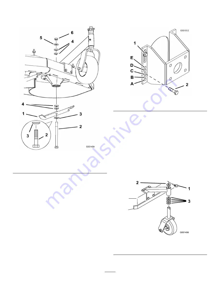
4. Hold the blade bolt and remove the nut. Slide the
bolt down through the spindle, and change the
spacers as needed (Figure 19).
Figure 19
1.
Blade
4.
Spacer
2.
Blade bolt
5.
Thin washer
3.
Curved washer
6.
Nut
5. Install the bolt, curved washer, blade, add extra
spacers, and secure them with a thin washer and a
nut (Figure 19).
6. Torque the blade bolt to 75-80 ft.-lb. (101-108 N•m).
Adjusting the Axle Height
Adjust the axle position to the selected height-of-cut
setting.
1. Disengage the PTO and pull the throttle to the stop
position.
2. Wait for all moving parts to stop before leaving the
operating position and then set the parking brake.
3. Place a jack under the rear center of the engine
frame. Raise the back end of the engine frame up
enough to remove the drive wheels.
4. Remove the drive wheels.
5. Loosen, but do not remove, the 2 top axle bolts
(Figure 20).
6. Remove the 2 lower axle bolts (Figure 20).
Figure 20
1.
Top axle bolt
2.
Lower axle bolt
7. Raise or lower the mounting bracket, so that you
can install the 2 axle adjustment bolts in the desired
hole location (Figure 20). A tapered punch can be
used to help align the holes.
8. Tighten all 4 bolts.
9. Install drive wheels and lower the mower.
Adjusting the Caster Position
1. Using the Height-of-Cut Chart, adjust the caster
spacers to match with the axle hole selected
(Figure 21).
Figure 21
1.
Latch pin
3.
Spacer, 1/2 inch (13 mm)
2.
Spacer, 3/16 inch (5 mm)
23
Summary of Contents for 30984
Page 7: ...Slope Chart 7...
Page 51: ...Schematics Electrical Schematic Rev Hydraulic Schematic Rev 51...
Page 52: ...Notes 52...
Page 53: ...Notes 53...
Page 54: ...Notes 54...


