background image

Inspecting the Transmission
Control Cable and Operating
Mechanism

Service Interval:

Every 250 hours

Check the condition and security of the cable and operating
mechanism at the speed-control pedals and transmission
pump ends.

Remove buildup of dirt, grit and other deposits.

Ensure that the ball joints are securely anchored and
check that the mounting brackets and cable anchors are
tight and free from cracks.

Inspect end fittings for wear, corrosion, broken springs,
and replace if necessary.

Ensure that the rubber seals are correctly located and are
in good condition.

Ensure that the articulating sleeves supporting the inner
cable are in good condition and firmly attached to the
outer cable assembly at the crimped connections. If there
are any signs of cracking or detachment install a new
cable immediately.

Check that sleeves, rods, and inner cable are free from
bends, kinks, or other damage. If they are not, install a
new cable immediately.

With the engine shut off, operate the pedal controls
through the entire range and ensure that the mechanism
moves smoothly and freely to the neutral position without
sticking or hanging up.
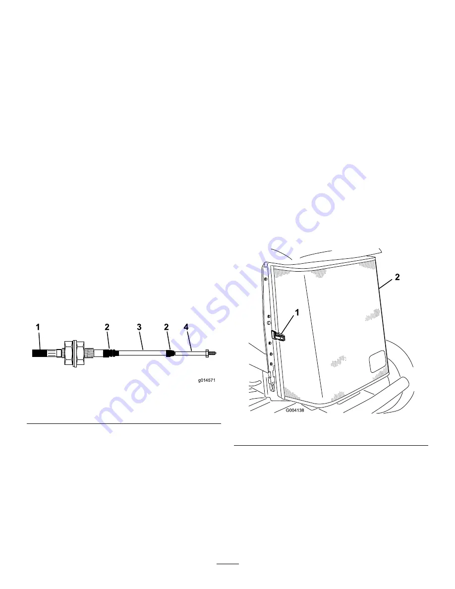
g014571

1                          2           3         2      4

Figure 58

1.

Outer cover

3.

Sleeve

2.

Rubber seal

4.

Rod end

Cooling System
Maintenance

Removing Debris from the
Cooling System

Service Interval:

Before each use or daily

Every 100 hours

Every 2 years

Note:

To prevent the engine from overheating, the radiator

and oil cooler must be kept clean. Normally, check daily and,
if necessary, clean any debris off these parts. However, it is
necessary to check and clean more frequently in extremely
dusty and dirty conditions.

1.

Turn the engine off and remove the key from the
ignition switch.

2.

Thoroughly clean all debris out of the engine area.

3.

Unlatch the clamp and pivot open the rear screen
(

Figure 59

).

Figure 59

1.

Rear screen latch

2.

Rear screen

4.

Clean the screen thoroughly with compressed air.

5.

Pivot the latches inward to release the oil cooler (

Figure

60

).

45


Summary of Contents for 30659 LT-F3000

Page 1: ...Form No 3401 570 Rev A LT F3000 Heavy Duty Triple Turf Flail Mower Model No 30659 Serial No 316000001 and Up Register at www Toro com Original Instructions EN 3401 570 A...

Page 2: ...s Service Department Spellbrook Bishops Stortford CM23 4BU England 44 0 1279 603019 Email uk service toro com Whenever you need service genuine Toro parts or additional information contact an Authoriz...

Page 3: ...System Maintenance 41 Draining the Fuel Tank 41 Checking the Fuel Lines and Connections 41 Bleeding the Fuel System 41 Replacing the Fuel Filter 42 Electrical System Maintenance 42 Checking the Electr...

Page 4: ...all objects which may be thrown by the machine Replace damaged or worn silencers mufflers Only use accessories and attachments approved by the manufacturer Before using always visually inspect to see...

Page 5: ...e Handling of Fuels To avoid personal injury or property damage use extreme care in handling fuel Fuel is extremely flammable and the vapors are explosive Extinguish all cigarettes cigars pipes and ot...

Page 6: ...ds and feet and throwing objects Always follow all safety instructions to avoid serious injury or death Use of this product for purposes other than its intended use could prove dangerous to user and b...

Page 7: ...d continued safety certification of the machine use only Toro replacement parts and accessories Replacement parts and accessories made by other manufacturers could be dangerous and such use could void...

Page 8: ...tting hazard of hand 2 Cutting hazard of foot 70 13 072 1 Jacking point 70 13 077 1 Warning shut off the engine and remove the ignition key before releasing or operating safety latches 950889 1 Warnin...

Page 9: ...platform latch is engaged before operating 111 3567 1 Pedal operation 111 3658 Rev B 111 3658 1 Cutterhead 3 Unlatch 2 Latch 111 3901 1 Transmission oil read the Operator s Manual for more informatio...

Page 10: ...e maximum level do not overfill 111 9648 1 Warning read the Operator s Manual torque the nuts to 45 N m 33 ft lb 117 3276 1 Engine coolant under pressure 3 Warning do not touch the hot surface 2 Explo...

Page 11: ...Thrown object hazard keep bystanders a safe distance from the machine 111 9649 1 Read the Operator s Manual for more information on service and maintenance 8 Ensure the blades stop when you leave the...

Page 12: ...the parts catalog to look up and order parts Declaration of Conformity 1 The Declaration of Conformity serves as confirmation of CE compliance Note Determine the left and right sides of the machine fr...

Page 13: ...c fluid warning light 18 Warning beacon switch supplied with beacon kit 9 Engine coolant warning light 19 Hour meter 10 Cutting unit drive switch 20 Auxiliary 12 V socket g014419 1 Figure 4 1 Weight t...

Page 14: ...rvice brake failure turn the ignition off to bring the mower to a standstill DANGER This machine is equipped with an emergency braking system which can cause ejection serious injury paralysis or even...

Page 15: ...utting units refer to Controlling the Position of the Individual Cutting Units page 28 Transport Latches Always raise the cutting units to the TRANSPORT position and secure with the transport latches...

Page 16: ...lever upward to adjust the forward backward position of the seat Release the lever to lock the seat in position Figure 11 1 G016377 Figure 11 1 Lever Operator weight adjustment Rotate the handle cloc...

Page 17: ...seat lift it beyond the highest setting then allow it to drop to the lowest setting Figure 13 G016379 Figure 13 Backrest adjustment Pull the handle outward to adjust the seat backrest angle Release th...

Page 18: ...ervoir exceeds 95 C 203 F refer to Figure 16 Figure 16 1 Hydraulic fluid temperature warning light Battery Charge Warning Light The battery charge warning light illuminates when the battery is low of...

Page 19: ...tant Attempting to start a cold engine before the preheat is used can cause unnecessary wear to the battery To start a cold engine refer to Starting a Cold Engine page 26 Figure 21 1 Engine preheat in...

Page 20: ...with cab Weight 1 380 kg 3 042 lb with ROPS 1 580 kg 3 483 lb with cab Engine Kubota 32 8 kw 44 hp at 3 000 rpm DIN 70020 Fuel tank capacity 45 7 L 12 US gallons Transport speed 25 km h 15 5 mph Mowin...

Page 21: ...r hearing protection when operating this machine The use of protective equipment for eyes ears hands feet and head is recommended G009027 1 2 Figure 26 1 Wear eye protection 2 Wear hearing protection...

Page 22: ...rag when opening the radiator cap and open the cap slowly to allow steam to escape The cooling system is filled with a 50 50 solution of water and permanent ethylene glycol antifreeze 1 Clean debris o...

Page 23: ...during fueling static electricity can be released causing a spark which can ignite the fuel vapors A fire or explosion from fuel can burn you and others and can damage property Always place fuel cont...

Page 24: ...ems and Toro cannot assume responsibility for unauthorized substitutions Note This synthetic fluid is not compatible with the Toro Biodegradable Fluid previously sold See your Toro Distributor for mor...

Page 25: ...started the operator must be seated before the parking brake is released for the engine to continue to run Flail Rotor Drive Lockout The drive to the flail rotors is only possible when the operator i...

Page 26: ...with a malfunction could cause serious damage If a warning light comes on during operation stop the machine immediately and correct the problem before continuing operation Starting a Warm Engine 1 Sit...

Page 27: ...usted depending on grass conditions and to not overload the power units or the heads The lower the forward speed the higher the quality of cut and after cut appearance Adjusting the Height of Cut Note...

Page 28: ...ote The control switches automatically return to position 2 NEUTRAL and the arms are hydraulically locked into position To raise the cutting units to the limited lift position momentarily operate the...

Page 29: ...mount of weight transfer can be varied to suit operating conditions by rotating the weight transfer hand wheel Figure 40 as follows 1 Release the valve locknut 1 2 turn counterclockwise and hold Figur...

Page 30: ...ing order Wear the seat belt when the roll bar is raised and no seat belt when the roll bar is lowered Important The roll bar is an integral and effective safety device Keep the roll bar in the raised...

Page 31: ...x plug 3 Locate the M12 x 40 mm setscrew and washer stored underneath the operator platform 1 in each of the platform support rails 4 Install a M12 x 40 mm long setscrew with washer into the hole in t...

Page 32: ...ows Note Ensure that the M12 x 40 mm setscrews and washers are removed and stored underneath the operator platform A Identify the right front wheel motor disc brake assembly B Rotate the setscrew coun...

Page 33: ...Always balance the quality of cut with the work rate required and set the forward speed accordingly Maximizing Engine Efficiency Do not let the engine labor If you notice that the engine starts to la...

Page 34: ...d radiator more frequently in dirty operating conditions Check the safety interlock system Check the hydraulic lines and hoses for leaks kinked lines loose mounting supports wear loose fittings weathe...

Page 35: ...he cooling system fluid Replace all moving hoses Replace the transmission cable contact your Authorized Toro Distributor Daily Maintenance Checklist Duplicate this page for routine use For the week of...

Page 36: ...Notation for Areas of Concern Inspection performed by Item Date Information 1 2 3 4 5 Important Refer to your engine operator s manual for additional maintenance procedures 36...

Page 37: ...e Toro service parts as these are accurately matched to the required duty Dirt and contamination are the enemies of any hydraulic system When carrying out maintenance procedures on the hydraulic syste...

Page 38: ...2 lithium grease Lubricate the bearings and bushings immediately after every washing regardless of the interval listed Replace any damaged grease fittings Important Use 1 pump of grease on the height...

Page 39: ...the indicator is red the air filter needs to be cleaned or replaced Figure 50 G014565 Figure 50 2 Before removing the filter use low pressure air 40 psi clean and dry to help remove large accumulation...

Page 40: ...r Service Interval After the first 50 hours Every 150 hours 1 Remove the drain plug Figure 52 and let the oil flow into a drain pan Figure 52 1 Oil drain plug 2 When the oil stops install the drain pl...

Page 41: ...ons have occurred Initial start up of a new machine Engine has ceased running due to lack of fuel Maintenance has been performed upon fuel system components i e filter replaced separator serviced etc...

Page 42: ...ugs from the electronic control module and the terminal connector from the alternator to prevent damage to the electrical system Checking the Electrical System Service Interval Every 500 hours Inspect...

Page 43: ...ke near the battery and keep sparks and flames away from it Check the battery condition Keep the terminals and the entire battery case clean because a dirty battery discharges slowly To clean the batt...

Page 44: ...12 to 0 31 inch Set the rear wheels in the straight ahead position Measure and compare the distance between the front sidewalls and the rear sidewalls at the wheel center height The distance between t...

Page 45: ...ks or other damage If they are not install a new cable immediately With the engine shut off operate the pedal controls through the entire range and ensure that the mechanism moves smoothly and freely...

Page 46: ...rnator belt by pressing it Figure 62 midway between the alternator and the crankshaft pulleys with 10 kg 22 lb of force Note The belt should deflect 11 mm 7 16 inch If the deflection is incorrect proc...

Page 47: ...t should illuminate and the engine should not start when the ignition key is turned Checking the Parking Brake Interlock Switch 1 Shut off the engine 2 Engage the parking brake 3 Turn the ignition key...

Page 48: ...nstall the drain plug with a new seal 3 Remove the oil tank suction flange to gain access to the suction strainer 4 Unscrew and remove the strainer and clean with paraffin or petrol before installing...

Page 49: ...ortant Blades should always be replaced at the same time as the opposite blade as pairs to maintain balance 1 Raise and support the cutting unit with the transport latches refer to Raising the Machine...

Page 50: ...se and secure the cutting units with the transport latches 2 If you are replacing blades on the center cutting unit remove the entire cutting unit unless an overhead lift is available 3 Turn the rotor...

Page 51: ...ecurely lock in the designated transport positions 4 Shut off the engine and remove the ignition key to isolate all power sources and check that they are stopped 5 Release all stored energy devices 6...

Page 52: ...page 53 2 Grip the rotor at each end and check for excessive end float Note If end float is detected contact your Authorized Service Dealer Note If the rotor needs to be replaced or balanced contact y...

Page 53: ...ely Minimum lift capacity 2 000 kg 4 409 lb 1 Park the mower on level ground 2 Set the parking brake 3 Shut off the engine and remove the key from the ignition switch 4 Ensure that the ground under th...

Page 54: ...e Toro Part No 505 47 or petroleum jelly to prevent corrosion D Slowly recharge the battery every 60 days for 24 hours to prevent lead sulfation of the battery Preparing the Engine 1 Drain the engine...

Page 55: ...ail rotor 1 Check and adjust the height of cut setting 2 The raise lower position control is not in the float position 2 Set the position control to the float position 3 There is no ground contact on...

Page 56: ...s The hydraulic oil system is overheating 7 There is a malfunctioning fan or fan drive 7 Check the fan operation and service it as required 1 There is a malfunctioning wheel motor brake assembly 1 Con...

Page 57: ...e the forward speed After an initial period of satisfactory operation the machine loses power 7 There are leaks on the suction hose 7 Check and tighten the fittings Replace the hose if necessary A fla...

Page 58: ...valve pressure checked Consult your authorized dealer 5 A flail rotor is jammed 5 Clear any jams as necessary 6 A cutting unit control valve is in the off position caused by malfunctioning control val...

Page 59: ...ndia 0091 44 2449 4387 Valtech Morocco 212 5 3766 3636 Jean Heybroek b v Netherlands 31 30 639 4611 Victus Emak Poland 48 61 823 8369 European Privacy Notice The Information Toro Collects Toro Warrant...

Page 60: ...eather storage practices contamination use of unapproved coolants lubricants additives fertilizers water or chemicals etc Normal noise vibration wear and tear and deterioration Normal wear and tear in...

Reviews: