25
Adjusting the Center Gage
Wheels
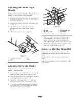
The gage wheels need to be adjusted in the proper hole
location for each height-of-cut position. There needs to be
3/8 inch (10 mm) clearance above the ground.
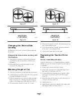
1. After adjusting height-of-cut, check the gage wheels so
that there is a minimum of 3/8 inch (10 mm) clearance
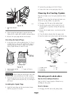
above the ground (Fig. 23).
2. If adjustment is needed, remove the bolt, washers and
nut (Fig. 23).
3. Select a hole position so the gage wheels are a
minimum of 3/8 inch (10 mm) off the ground
(Fig. 23).
4. Install the bolt, washers and nut (Fig. 23).
1
2
3
4
4
m–6366
Figure 23
1.
Center Gage Wheels and
Spacer
2.
Nut
3.
Bolt
4.
Washer
Adjusting the Handle Height
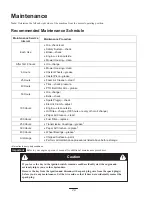
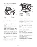
The handle position can be adjusted to match the
operator ’s height preference.
1. Remove hairpin cotter, washer and clevis pin securing
control rod fitting to idler bracket (Fig. NO TAG).
2. Loosen the upper flange bolts (3/8 x 1 inch) and flange
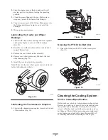
nut securing handle to rear frame (Fig. 24).
3. Remove the lower flange bolts (3/8 x 1 inch) and
flange nuts securing handle to rear frame (Fig. 24).
4. Pivot handle to desired operating position and install
lower flange bolts (3/8 x 1 inch) and flange nuts into
mounting holes. Tighten all flange bolts.
1
2
3
4
8
7
5
6
m–6403
Figure 24
1.
Upper handle
2.
Rear frame
3.
Flange nut, 3/8 inch
4.
Flange bolt, 3/8 x 1 inch
5.
Upper mounting hole
6.
Lower mounting holes
7.
Low position
8.
High position
5. Thread rod fitting up or down on rod until proper
position is attained and install into fitting to idler
bracket with clevis pin, washer and hairpin cotter.
Refer to Installing the Control Rod on page NO TAG.
6. Check the parking brake adjustment (Fig. NO TAG).
Refer to Checking the Brakes, page 32.
Using the Mid–Size Weight Kit
A weight kit is available for this machine. This kit is
optional and can be obtain from an Authorized Service
Dealer.
Installing this weight kit can improve performance on
slopes.
Note: For this machine install the weight kit only in the
front position.


