background image

Brake Maintenance

Adjusting the Parking Brake

If the parking brake does not hold securely, an adjustment
is required.

1.

Park the machine on a level surface.

2.

Turn the key in the ignition switch to the O

FF

position

and wait for all moving parts to stop.

3.

Check the air pressure in the drive tires.

Note:

If needed, adjust to the recommended inflation;

refer to

Checking the Air Pressure in the Tires (page

38)

.

4.

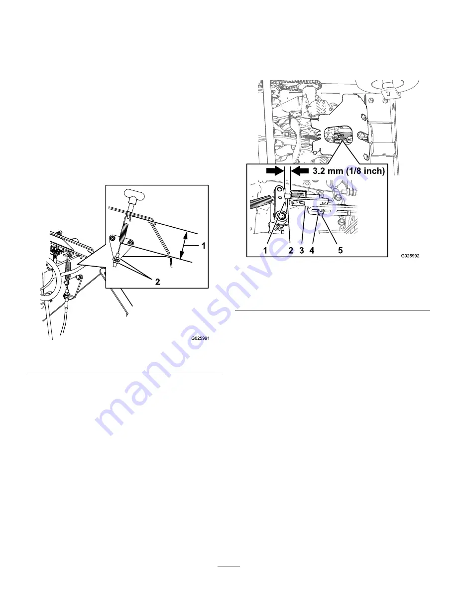
Loosen the jam nut on the brake cable under the
console (

Figure 52

).

Figure 52

1.

7.9 cm (3–1/8 inch)

5.

Set the parking brake (

Figure 52

).

6.

Adjust the jam nut position until 7.9 cm (3–1/8 inch)
from the bottom of the link to the bottom of the spring
(

Figure 52

).

7.

Secure the adjustment of the cable by tightening the
jam nuts (

Figure 52

).

8.

Check the parking brake; if necessary, repeat steps

4

through

7

.

Adjusting the Brake Switch

1.

Park the machine on a level surface.

2.

Turn the key in the ignition switch to the O

FF

position

and wait for all moving parts to stop.

3.

Prior to adjusting the brake switch, ensure the parking
brake is properly adjusted; refer to

Adjusting the

Parking Brake (page 41)

.

4.

Set the parking brake.

5.

Check the distance between the parking brake-switch
bracket to the brake arm of the transmission (

Figure

53

).

Note:

The distance should be 3.2 mm (1/8 inch).

Figure 53

1.

Brake arm (transmission)

4.

Locknut

2.

Plunger (brake switch)

5.

Carriage bolt

3.

Brake-switch bracket

6.

If adjustment is required, preform the following:

A.

Loosen the locknut and carriage bolt securing the
parking brake switch bracket (

Figure 53

).

B.

Adjust the position of the brake-switch bracket
until the gap (

Figure 53

between the switch

bracket and the brake arm is 3.2 mm (1/8 inch)

C.

Tighten the locknut and carriage bolt (

Figure 53

)

securing the brake-switch bracket to 1017 to 1243
N-cm (90 to 110 lb-in).

41


Summary of Contents for 23518

Page 1: ...Form No 3397 997 Rev A 30in Stand On Aerator Model No 23518 Serial No 316000001 and Up Model No 39518 Serial No 316000001 and Up Register at www Toro com Original Instructions EN 3397 997 A...

Page 2: ...and commercial grounds Read this information carefully to learn how to operate and maintain your product properly and to avoid injury and product damage You are responsible for operating the product...

Page 3: ...rester if equipped 35 Fuel System Maintenance 35 Servicing the Fuel Filter 35 Electrical System Maintenance 36 Servicing the Battery 36 Servicing the Fuses 38 Drive System Maintenance 38 Checking the...

Page 4: ...ng material Note If the operator s or mechanic s cannot read the manual language it is the owner s responsibility to explain this material to them Become familiar with the safe operation of the equipm...

Page 5: ...as a portable container rather than from a fuel dispenser nozzle Keep the nozzle in contact with the rim of the fuel tank or container opening at all times until fueling is complete Do not use a nozzl...

Page 6: ...the drive wheels may result in sliding and a loss of braking and steering Do not aerate slopes greater than 15 degrees Avoid sudden starts and stops when aerating uphill because the machine may tip ba...

Page 7: ...degrees Use the slope chart to determine the degree of slope of hills before operating Do not operate this machine on a slope greater than 15 degrees Fold along the appropriate line to match the recom...

Page 8: ...2047 1 Warning do not touch the hot surface 116 9391 117 2718 120 9570 1 Warning stay away from moving parts keep all guards and shields in place 121 6150 1 Cutting hazard of hand and foot stay away f...

Page 9: ...ral 8 Choke on 13 Thrown object hazard pick up debris before operating the machine 4 Reverse 9 Choke off 14 Warning keep away from moving parts keep all guards in place 5 Wheels and tines rotate when...

Page 10: ...dth ramps to load a machine for transport use a loading ramp at a maximum of 15 degrees 2 Tipping hazard do not operate the machine on slopes greater than 15 degrees do not operate the machine near dr...

Page 11: ...e machine is shipped with a filled lead acid battery DANGER Charging or jump starting the battery may produce explosive gases Battery gases can explode causing serious injury Keep sparks flames or cig...

Page 12: ...sparks and engagement of components Sparks could cause an explosion or moving parts could accidentally engage causing personal injury Be sure ignition switch is in the OFF position before charging th...

Page 13: ...refer to Choke Lever page 14 6 Turn the key in the ignition switch to the START position refer to Ignition Switch page 15 Note Release the switch as soon as the engine starts Important Do not crank th...

Page 14: ...e pressure control to adjust the downward pressure on the tines and core depth Rotate the control counterclockwise to decrease the pressure and the length of the aeration plug rotate clockwise to incr...

Page 15: ...tine down pressure control on the control console To enable the tines ground engagement push down on the top of the switch To disable the tines ground engagement push down on the rear of the switch Ti...

Page 16: ...ck to the operating position move the lever to the larger opening of the slot push inward until the washer is inside the frame then move the lever back to the narrow portion of the slot Repeat this on...

Page 17: ...performance problems and or engine damage which may not be covered under warranty Do not use gasoline containing methanol Do not store fuel either in the fuel tank or fuel containers over the winter...

Page 18: ...h soap and water Using Stabilizer Conditioner Use a fuel stabilizer conditioner in the machine to provide the following benefits Keeps gasoline fresh during storage of 90 days or less For longer stora...

Page 19: ...the machine to fall which could cause injury Do not rely solely on mechanical or hydraulic jacks for support Use adequate jack stands or equivalent support 3 Turn the key in the ignition switch to the...

Page 20: ...the Engine 1 Move the traction control levers to the NEUTRAL position and set the parking brake refer to Traction Control Levers page 14 and Parking Brake Handle page 15 Note To start the engine the...

Page 21: ...oot switch control to raise the tines refer to Raising the Tines page 21 3 Place the throttle in the midway between the SLOW and FAST positions refer to Throttle Lever page 14 4 Allow the engine to ru...

Page 22: ...on control levers to the NEUTRAL OPERATE position 2 To move rearward in a straight line slowly move both levers rearward with equal pressure Figure 20 To turn left or right release pressure on the tra...

Page 23: ...to Traction Control Levers page 14 4 Adjust the throttle for the working conditions refer to Throttle Lever page 14 Adjusting the Tine Down Pressure Important Keep the drive tires on the ground at all...

Page 24: ...can be moved Figure 24 1 Left traction control lever 5 Forward 2 Right traction control lever 6 Neutral 3 Front reference bar 7 Reverse 4 Front of the machine Driving Forward 1 Make sure the traction...

Page 25: ...icable connect the trailer brakes 4 Load the machine onto the trailer or truck 5 Stop the engine remove the key set the brake and close the fuel valve 6 Set the parking brake and block the tires 7 Use...

Page 26: ...trailer or a truck Avoid sudden acceleration while driving machine up a ramp to avoid tipping backward Avoid sudden deceleration while backing machine down a ramp to avoid tipping backward Figure 28...

Page 27: ...for loose hardware Check the tines Clean the engine and the exhaust system area Clean the grass and debris buildup from the machine Every 25 hours Grease the jackshaft bearings Grease the wheel beari...

Page 28: ...nical or hydraulic jacks for support Use adequate jack stands or equivalent support Preparing for the Machine for Maintenance Perform the following before servicing cleaning or making any adjustments...

Page 29: ...ooze out of the bearings 5 Wipe up any excess grease Lubricating the Casters Grease type National Lubricating Grease Institute NGLI grade 2 multi purpose gun grease Greasing the Caster Pivots Service...

Page 30: ...he wheel Figure 33 2 Install the bearing seal into the hub at the bearing Figure 33 3 If you removed or broke loose both of the spacer nuts from the axle assembly perform the following A Clean the thr...

Page 31: ...t if it is worn or damaged 2 Wash the foam element in liquid soap and warm water When the element is clean rinse it thoroughly 3 Dry the element by squeezing it in a clean cloth Servicing the Paper Ai...

Page 32: ...tely 2 Stop the engine set the parking brake remove the key and wait for all moving parts to stop before leaving the operating position 3 Change the engine oil as shown in Figure 37 Note Torque drain...

Page 33: ...oil filter to soak up any spilled oil Important Spilled oil may drain under the engine and onto the clutch Oil spilled on the clutch may damage the clutch cause the blades to stop slowly when the clu...

Page 34: ...t the air gap Install a new spark plug s if necessary Removing the Spark Plug 1 Stop the engine set the parking brake remove the key and wait for all moving parts to stop before leaving the operating...

Page 35: ...e brush Note Soak the arrester screen in solvent if necessary C Install spark arrester onto exhaust outlet Fuel System Maintenance Servicing the Fuel Filter Replacing the Fuel Filter Service Interval...

Page 36: ...ies contain lead and lead compounds chemicals known to the State of California to cause cancer and reproductive harm Wash hands after handling DANGER Do not drink electrolyte and avoid contact with sk...

Page 37: ...move the battery Installing the Battery 1 Place the battery onto the machine Figure 44 2 Secure the battery to the battery tray with the battery strap 3 Install the positive red battery cable to posit...

Page 38: ...he fuse block Figure 46 5 Install the negative battery cable from the battery terminal refer to steps 5 and 6 of Installing the Battery page 37 Drive System Maintenance Checking the Air Pressure in th...

Page 39: ...pport 3 Check the chains on both sides of the machine for proper tension Note The chains should move up and down 6 to 12 mm 1 4 to 1 2 inch 4 At each side of the machine loosen the 3 nuts and bolts th...

Page 40: ...that secure the idler sprocket Figure 50 5 Increase or decrease chain tension by performing the following Push down and forward on the sprocket to increase the chain tension as shown in Figure 50 Lift...

Page 41: ...ough 7 Adjusting the Brake Switch 1 Park the machine on a level surface 2 Turn the key in the ignition switch to the OFF position and wait for all moving parts to stop 3 Prior to adjusting the brake s...

Page 42: ...the parking brake remove the key and wait for all moving parts to stop before leaving the operating position 2 Loosen the locknut 3 8 inch that secures the auxiliary pump idler pulley to the chassis o...

Page 43: ...the control lever all the way forward to the front reference bar 4 If the control lever contact the reference bar or do not contact the reference bar perform the following A Release the control lever...

Page 44: ...ole pad refer to Removing the Console Pad page 28 5 Clean area around hydraulic reservoir cap Figure 58 Figure 58 1 Cold oil level 2 Hot oil level 6 Remove the cap and check hydraulic oil level in the...

Page 45: ...emove the inlet hose from the hydraulic fitting in the pump place the end of the hose in a drain container and allow oil to drain Figure 60 Figure 60 1 Hydraulic fitting auxiliary hydraulic pump 3 Dra...

Page 46: ...contaminated or been extremely hot 1 Stop the engine set the parking brake remove the key and wait for all moving parts to stop before leaving the operating position 2 Raise the machine and support i...

Page 47: ...ransmission Oil Level page 46 5 Install the sight plug and torque it to 244 N m 180 in lb 6 Repeat steps 3 through 5 for the other transmission 7 Add the specified oil into the expansion tank until th...

Page 48: ...the rear cover panel to the holes in the chassis Figure 66 7 Secure the cover panel to the chassis with the 2 bolts and 2 washers Figure 66 that you removed in step 3 and torque the bolts to 37 to 45...

Page 49: ...from the Machine Service Interval Before each use or daily 1 Stop the engine set the parking brake remove the key and wait for all moving parts to stop before leaving the operating position 2 Clean o...

Page 50: ...c drive 3 Service the air cleaner refer to Servicing the Air Cleaner page 31 4 Lubricate the machine refer to Lubricating the Grease Fittings page 29 5 Change the engine oil refer to Changing the Engi...

Page 51: ...nections for good contact Clean connector terminals thoroughly with electrical contact cleaner apply dielectric grease and reconnect 8 A relay or switch is faulty 8 Contact an Authorized Service Deale...

Page 52: ...ns are not properly tensioned 7 Check the jackshaft drive chain tension the drive wheel chain tension and the tine drive chain tension 1 There is an auxiliary pump belt problem 1 Tension or replace th...

Page 53: ...Schematics Electrical Diagram Rev A 53...

Page 54: ...Electrical Schematic Rev A 54...

Page 55: ...Hydraulic Diagram Rev A 55...

Page 56: ...quired maintenance and or adjustments Repairs necessary due to failure to follow recommended fuel procedure consult Operator s Manual for more details Removing contaminants from the fuel system is not...

Reviews: