chance of varnish deposits in the fuel system, use fuel
stabilizer at all times.
Filling the Fuel Tank
1. Park the traction unit on a level surface, lower the
loader arms, and stop the engine.
2. Remove the key and allow the engine to cool.
3. Clean around the fuel tank cap and remove it.
4. Add unleaded gasoline to the fuel tank, until the
level is just below the bottom of the filler neck.
Important:
This space in the tank allows
gasoline to expand. Do not fill the fuel tank
completely full.
5. Install the fuel tank cap securely.
6. Wipe up any gasoline that may have spilled.
Checking the Engine Oil Level
Service Interval:
Before each use or daily
1. Park the traction unit on a level surface, lower the
loader arms, and stop the engine.
2. Remove the key and allow the engine to cool.
3. Open the hood.
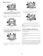
4. Clean around the oil dipstick (Figure 17).
Figure 17
1.
Oil dipstick
2.
Metal end
5. Pull out the dipstick and wipe the metal end clean
6. Slide the dipstick fully into the dipstick tube
7. Pull the dipstick out and look at the metal end.
8. If the oil level is low, clean around the oil filler cap
and remove the cap (Figure 18).
Figure 18
1.
Filler cap
2.
Valve cover
9. Slowly pour only enough oil into the valve cover to
raise the level to the F (full) mark.
Important:
Do not overfill the crankcase with
oil because the engine may be damaged.
10. Replace the filler cap and dipstick.
11. Close the hood.
Checking the Hydraulic Fluid
Level
Service Interval:
Every 25 hours
Hydraulic Tank Capacity: 12 US gallons (45.4 l)
Use 10W-30 or 15W-40 detergent, diesel engine oil (API
service CH-4 or higher).
1. Remove the attachment, if one is installed; refer to
Removing an Attachment.
2. Park the traction unit on a level surface, lower the
loader arms, and fully retract the tilt cylinder.
3. Stop the engine, remove the key, and allow the
engine to cool.
4. Open the hood.
5. Clean the area around the filler neck of the hydraulic
tank (Figure 19).
6. Remove the cap from the filler neck and check the
fluid level on the dipstick (Figure 19).
The fluid level should be between the marks on the
dipstick.
20
Summary of Contents for 22331 TX 420
Page 7: ...Slope Chart 7 ...
Page 48: ...Schematics Electrical Schematic Rev A 48 ...
Page 49: ...Hydraulic Schematic Rev A 49 ...
Page 50: ...Notes 50 ...
Page 51: ...Notes 51 ...


