


Drive System
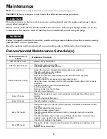
Maintenance
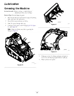
Servicing the Tracks
Service Interval:
After the first 50 hours—Check and adjust
the track tension.
Before each use or daily—Clean the tracks.
Before each use or daily—Check the tracks for
excessive wear and proper tension.
Every 100 hours—Check and adjust the track tension.
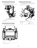
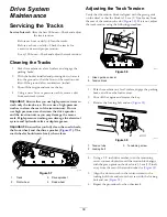
Cleaning the Tracks
1.
Park the machine on a level surface and engage the
parking brake.
2.
With the bucket installed and pointing down, lower it
into the ground so that the front of the traction unit
lifts off the ground a few centimeters (inches).
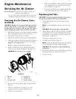
3.
Shut off the engine and remove the key.
4.
Using a water hose or pressure washer, remove dirt
from each track system.
Important:
Ensure that you use high-pressure water to
wash only the track area. Do not use a high-pressure
washer to clean the rest of the traction unit. Do not
use high pressure water between the drive sprocket
and the traction unit or you may damage the motor
seals. High-pressure washing can damage the electrical
system and hydraulic valves or deplete grease.
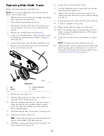
Important:
Ensure that you fully clean the road wheels,
the front wheel, and the drive sprocket (
). The
road wheels should rotate freely when clean.
g029756
Figure 57
1.
Track
3.
Drive sprocket
2.
Front wheel
4.
Road wheel
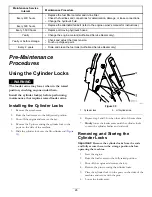
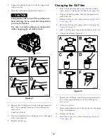
Adjusting the Track Tension
Verify that the tension block is aligned with the green guide
on the decal or that the block is 1.3 cm (1/2 inch) away from
the rear of the tension tube slot (
). If it is not, adjust
the track tension using the following procedure:
g203962
Figure 58
1.
Green guide on decal
2.
Tension block
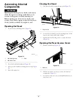
1.
Park the machine on a level surface, engage the parking
brake, and lower the loader arms.
2.
Shut off the engine and remove the key.
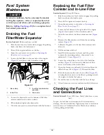
3.
Remove the locking bolt and nut (
g029758
Figure 59
1.
Tension tube
3.
Tensioning screw
2.
Locking bolt
4.
Using a 1/2 inch drive ratchet, turn the tensioning
screw counter-clockwise until the tension block aligns
with the green guide on the decal or is 1.3 cm (1/2 inch)
away from the rear of the tension tube slot (
5.
Align the closest notch in the tension screw to the
locking-bolt hole and secure the screw with the locking
bolt and nut (
6.
Repeat the procedure for the other track.
39
Summary of Contents for 22327
Page 54: ...Schematics g205307 Electrical Schematic Rev B 54...
Page 55: ...g206362 Hydraulic Schematic Rev B 55...
Page 56: ...Notes...
Page 57: ...Notes...
Page 58: ...Notes...


