background image

Transporting the Machine

Use a heavy-duty trailer or truck to transport the machine.
Use full-width ramps. Ensure that the trailer or truck has all
the necessary brakes, lighting, and marking as required by law.
Please carefully read all the safety instructions. Knowing this
information could help you, your family, pets, or bystanders
avoid injury. Refer to your local ordinances for trailer and
tie-down requirements.

WARNING

Driving on the street or roadway without
turn signals, lights, reflective markings, or a
slow-moving-vehicle emblem is dangerous and can
lead to accidents causing personal injury.

Do not drive the machine on a public street or
roadway.

Selecting a Trailer

WARNING

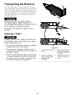
Loading a machine onto a trailer or truck increases
the possibility of tip-over and could cause serious
injury or death (

Figure 29

).

Use only a full-width ramp; do not use individual
ramps for each side of the machine.

Do not exceed a 15-degree angle between the
ramp and the ground or between the ramp and
the trailer or truck.

Ensure that the length of ramp is at least 4 times
as long as the height of the trailer or truck bed to
the ground. This ensures that ramp angle does
not exceed 15 degrees on flat ground.

g027996

5

1

2

6

g027996

Figure 29

1.

Full-width ramp in stowed
position

4.

Ramp is at least 4 times
as long as the height of
the trailer or truck bed to
the ground

2.

Side view of full-width
ramp in loading position

5.

H=height of the trailer or
truck bed to the ground

3.

Not greater than
15 degrees

6.

Trailer

23


Summary of Contents for 22327

Page 1: ...27 Serial No 400414000 and Up Model No 22327G Serial No 400414000 and Up Model No 22327HD Serial No 400414000 and Up Model No 22328 Serial No 400414000 and Up Model No 22328HD Serial No 400414000 and...

Page 2: ...Replacements may be ordered through the engine manufacturer Introduction This machine is a compact tool carrier intended to move various earth and materials for landscaping and construction work It i...

Page 3: ...g the Engine Oil 31 Fuel System Maintenance 33 Draining the Fuel Filter Water Separator 33 Replacing the Fuel Filter Canister and In Line Filter 33 Checking the Fuel Lines and Connections 33 Bleeding...

Page 4: ...ropriate clothing including gloves eye protection long pants substantial slip resistant footwear and hearing protection Tie back long hair and do not wear jewelry Inspect the area where you will use t...

Page 5: ...ur machine Lightning can cause severe injury or death If lightning is seen or thunder is heard in the area do not operate the machine seek shelter Slope Operation Slopes are a major factor related to...

Page 6: ...ls If any maintenance or repair requires the loader arms to be in the raised position secure the arms in the raised position with the hydraulic cylinder lock s Secure the loader arm valve with the loa...

Page 7: ...ill rating of B a Rear Uphill rating of D and a Side Uphill rating of C then you could drive forward up a 19 slope rearward up a 11 slope or sideways on a 11 slope as listed in the following table Mod...

Page 8: ...a section Use the slope indicator to determine the degree of slope of hills before operating Do not operate this machine on a slope greater than that specified in the Stability Data section Fold along...

Page 9: ...g do not touch the hot surface decal115 4855 115 4855 1 Hot surface burn hazard wear protective gloves when handling the hydraulic couplers and read the Operator s Manual for information on handling h...

Page 10: ...pressure 7 Parking brake disengaged 3 Blinking light glow plug 8 Traction neutral 4 Steady light battery warning 9 Auxiliary lever neutral 5 Hourmeter decal131 0709 131 0709 1 Parking brake engage 2...

Page 11: ...decal136 5750 136 5750 1 Read the Operator s Manual 2 Tension block guide decal131 0597 131 0597 decal131 0708 131 0708 1 Move forward 3 Move rearward 2 Turn right 4 Turn left 11...

Page 12: ...ine 10 Tipping hazard always move up or down slopes with the bucket lowered never drive on a slope with the bucket raised always operate with the heavy end uphill always carry loads low never jerk the...

Page 13: ...Key switch 3 Reference bar 8 Traction control 4 Plug 9 Loader arm attachment tilt lever 5 Auxiliary hydraulics lever 10 Loader lock Key Switch The key switch used to start and shut off the engine has...

Page 14: ...g look behind you for obstructions and keep your hands on the reference bar g029286 Figure 8 To turn right rotate the traction control clockwise Figure 9 g029288 Figure 9 To turn left rotate the tract...

Page 15: ...so that you cannot push it forward This helps to ensure that no one accidentally lowers the loader arms during maintenance Secure the loader arms with the lock anytime you need to shut off the machin...

Page 16: ...uel in the fuel tank s Message Display Engine Coolant Temperature Light If the engine coolant becomes too hot the light on the left flashes and the horn sounds Figure 16 If this happens disengage the...

Page 17: ...m 61 inches Reach fully raised with standard bucket 62 cm 25 inches Height to hinge pin with standard bucket in highest position 206 cm 81 inches Model 22328 Width 103 cm 41 inches Length 256 cm 101 i...

Page 18: ...ill the fuel tanks outdoors in an open area when the engine is cold Wipe up any fuel that spills Never fill the fuel tanks inside an enclosed trailer Never smoke when handling fuel and stay away from...

Page 19: ...Biodiesel Ready This machine can also use a biodiesel blended fuel of up to B20 20 biodiesel 80 petrodiesel The petrodiesel portion should be low or ultra low sulfur Observe the following precautions...

Page 20: ...ON When reversing you may back into stationary objects or over bystanders and cause serious personal injury or death Look behind you for obstructions or bystanders and keep your hands on the reference...

Page 21: ...he attachment on a level surface with enough space behind it to accommodate the machine 2 Start the engine 3 Tilt the attachment mount plate forward 4 Position the mount plate into the upper lip of th...

Page 22: ...he key 2 Move the auxiliary hydraulics lever forward backward and back to the NEUTRAL position to relieve pressure at the hydraulic couplers 3 Remove the protective covers from the hydraulic connector...

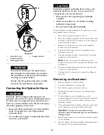
Page 23: ...y Selecting a Trailer WARNING Loading a machine onto a trailer or truck increases the possibility of tip over and could cause serious injury or death Figure 29 Use only a full width ramp do not use in...

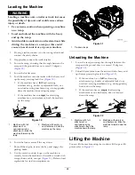
Page 24: ...chment or non load carrying attachment drive the machine forward up the ramp 2 Machine with empty or no attachment back the machine up the ramp 6 Lower the loader arms all the way down 7 Shut off the...

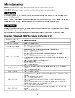
Page 25: ...chine Grease immediately after every washing Check the air filter service indicator Check the engine oil level Drain water and other contaminants from the fuel filter water separator Clean the tracks...

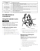
Page 26: ...aintenance that requires raised loader arms Installing the Cylinder Locks 1 Remove the attachment 2 Raise the loader arms to the fully raised position 3 Shut off the engine and remove the key 4 Remove...

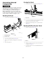
Page 27: ...er 2 Turn the hood latch clockwise Figure 34 3 Lift up on the handles and swing the hood up Figure 34 4 Secure the prop rod Closing the Hood 1 Lift up on the tab securing the prop rod Figure 35 g03121...

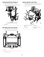
Page 28: ...een Removing the Front Screen 1 Open the hood and secure the hood prop 2 Loosen the 2 top bolts and 2 front bolts g031218 Figure 38 1 Bolt 3 Remove the screen Removing the Front Cover 1 Remove the 2 u...

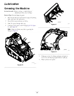
Page 29: ...oader arms 2 Shut off the engine and remove the key 3 Clean the grease fittings with a rag 4 Connect a grease gun to each fitting Figure 40 Figure 41 and Figure 42 Note Raise the loader arms before gr...

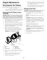
Page 30: ...over 6 Service indicator 6 Squeeze the dust cap sides to open it and knock the dust out 7 Clean the inside of the air cleaner cover with compressed air that is under 205 kPa 30 psi 8 Check the service...

Page 31: ...on a level surface engage the parking brake and lower the loader arms 2 Shut off the engine remove the key and allow the engine to cool 3 Open the hood and secure the prop rod 4 Clean the area around...

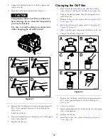
Page 32: ...cap Changing the Oil Filter 1 Raise the loader arms and secure with the cylinder locks refer to Installing the Cylinder Locks page 26 2 Engage the parking brake shut off the engine and remove the key...

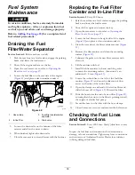
Page 33: ...n the rear access cover refer to Opening the Rear Access Cover page 27 4 Locate the fuel filters on the right side of the engine Figure 49 and place a clean container under it 5 Clean the area where t...

Page 34: ...chemicals known to the State of California to cause cancer and reproductive harm Wash hands after handling Important Before welding on the machine disconnect the negative cable from the battery WARNI...

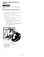
Page 35: ...key 3 Open the hood secure the prop rod and remove the left side screen 4 Turn the battery disconnect switch to the ON or OFF position to perform the following To energize the machine electrically ro...

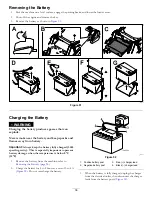
Page 36: ...he battery fully charged 1 265 specific gravity This is especially important to prevent battery damage when the temperature is below 0 C 32 F 1 Remove the battery from the machine refer to Removing th...

Page 37: ...a solution of baking soda and water 5 Rinse the battery with clear water 6 Coat the battery posts and cable connectors with Grafo 112X skin over grease Toro Part No 505 47 or petroleum jelly to preven...

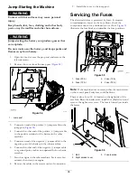
Page 38: ...nnect the other end of the negative jumper cable to a ground point such as an unpainted bolt or chassis member 7 Start the engine in the other machine Let it run a few minutes then start your engine 8...

Page 39: ...or deplete grease Important Ensure that you fully clean the road wheels the front wheel and the drive sprocket Figure 57 The road wheels should rotate freely when clean g029756 Figure 57 1 Track 3 Dri...

Page 40: ...m the drive sprocket and road wheels Figure 60 9 Beginning at the drive sprocket coil the new track around the sprocket ensuring that the lugs on the track fit between the spacers on the sprocket Figu...

Page 41: ...side the wheels then fill this area on each side of each wheel with grease 11 Install the large washers on the wheels over the grease 12 Install the new track Figure 62 Note Ensure that the lugs in th...

Page 42: ...ut off the engine and remove the key from the key switch before performing maintenance CAUTION Swallowing engine coolant can cause poisoning Do not swallow engine coolant Keep out of reach from childr...

Page 43: ...ive the machine forward or rearward 4 If the machine moves contact your Authorized Toro Dealer for service Belt Maintenance Checking the Alternator Fan Belt Tension Service Interval Every 100 hours Ch...

Page 44: ...petrolium based products The specifications must fall within the listed range for all the following material properties and the fluid should meet the listed industry standards Check with your hydraul...

Page 45: ...pen the hood and secure the prop rod 6 Remove the right side screen 7 Clean the area around the filler neck of the hydraulic tank Figure 64 g029748 Figure 64 1 Filler neck cap 8 Remove the filler neck...

Page 46: ...d within a few hours by a doctor familiar with this form of injury otherwise gangrene may result Keep your body and hands away from pinhole leaks or nozzles that eject high pressure hydraulic fluid Us...

Page 47: ...if necessary refer to Checking the Hydraulic Fluid Level page 45 14 Close the hood Checking the Hydraulic Lines Service Interval Every 100 hours Check the hydraulic lines for leaks loose fittings kin...

Page 48: ...is Service Interval Every 100 hours Check for dirt buildup in the chassis Over time the chassis under the engine collects dirt and debris that must be removed Using a flashlight open the hood and insp...

Page 49: ...30 5 Grease the machine refer to Greasing the Machine page 29 6 Change the engine oil refer to Changing the Engine Oil page 31 7 Charge the battery refer to Charging the Battery page 36 8 Check and a...

Page 50: ...uel line is clogged 5 Clean or replace the fuel line 6 There is air in the fuel 6 Bleed the nozzles and check for air leaks at the fuel hose connections and fittings between the fuel tank and engine 7...

Page 51: ...ir in the fuel 3 Bleed the nozzles and check for air leaks at the fuel hose connections and fittings between the fuel tank and engine 4 The injection nozzles are damaged 4 Contact your Authorized Serv...

Page 52: ...l is in the fuel system 4 Drain and flush the fuel system add fresh fuel 5 The engine is overheating 5 Refer to The engine overheats 6 The spark arrestor screen is clogged 6 Clean or replace the spark...

Page 53: ...ompression 6 Contact your Authorized Service Dealer 1 The parking brake is engaged 1 Disengage the parking brake 2 The hydraulic fluid level is low 2 Add hydraulic fluid to the reservoir 3 The hydraul...

Page 54: ...Schematics g205307 Electrical Schematic Rev B 54...

Page 55: ...g206362 Hydraulic Schematic Rev B 55...

Page 56: ...Notes...

Page 57: ...Notes...

Page 58: ...Notes...

Page 59: ...these activities We will not sell your personal information to any other company We reserve the right to disclose personal information in order to comply with applicable laws and with requests by the...

Page 60: ...s filters gaskets wear plates seals O rings drive chains clutches Failures caused by outside influence Items considered to be outside influence include but are not limited to weather storage practices...

Reviews: