Toro 136-9045 Installation Instructions Manual Download Page 3

Assembling the Kit

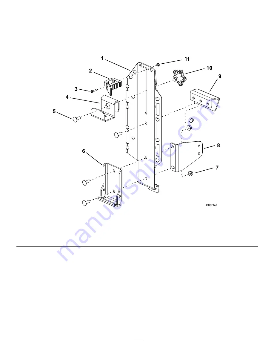
Assemble the kit as shown in

Figure 2

. Ensure to loosely install the upper mount to the main bracket; refer to

Figure 3

to determine which hole to use in the upper mount.

Note:

Install the lower support bracket only if you are mounting the kit in front of the rear tires. Install the

bracket so that the large face is oriented rearward on the machine;

Figure 2

or shows the bracket orientation

for mounting the kit on the left side of the machine.

g037140

Figure 2

1.

Main bracket

4.

Top bracket

7.

Nut (5/16 inch)

10.

Knob

2.

Fist clamp (optional)

5.

Carriage bolt (5/16 x 7/8
inch)

8.

Lower support bracket (if
needed)

11.

Locknut (#8)

3.

Slotted screw

6.

Welded support bracket

9.

Upper mount

Note:

Mounting the fist clamp is optional. If mounting the fist clamp to the main bracket is inconvenient for

mounting some accessories, you may alternatively mount it to a bucket (sold separately); drill a hole (5.1 mm or
0.2 inch diameter) into the bucket and mount the fist clamp to it using the slotted screw and locknut.

3


Summary of Contents for 136-9045

Page 1: ...h defects or reproductive harm Safety Safety and Instructional Decals Safety decals and instructions are easily visible to the operator and are located near any area of potential danger Replace any de...

Page 2: ...1 Install the kit Bolt 5 16 x 1 inch 3 Nut 5 16 inch use only 4 for 2017 and older machines 6 Carriage bolt 5 16 x 7 8 inch use only 1 for 2017 and older machines 4 Inner support bracket 2018 and new...

Page 3: ...tion for mounting the kit on the left side of the machine g037140 Figure 2 1 Main bracket 4 Top bracket 7 Nut 5 16 inch 10 Knob 2 Fist clamp optional 5 Carriage bolt 5 16 x 7 8 inch 8 Lower support br...

Page 4: ...ocation behind the rear tires Mounting the Kit to the Machine Mounting Locations You can mount this kit in 6 locations on the machine Figure 4 Refer to 1 of the following procedures to mount the kit i...

Page 5: ...inch and 1 nut 5 16 inch as shown in Figure 5 or Figure 6 Note You will not use the bottom hole in the main bracket or lower support bracket Note Ensure that the assembly is vertical If it hangs at an...

Page 6: ...bolts 5 16 x 7 8 inch and 2 nuts 5 16 inch as shown in Figure 7 When installing the inner support bracket on the left side of the machine orient the inner support bracket as shown in Figure 8 When in...

Page 7: ...6 inch as shown in Figure 10 Note You will not use the bottom hole in the main bracket or lower support bracket Note Ensure that the assembly is vertical If it hangs at an angle the lower support brac...

Page 8: ...engine guard using 1 carriage bolt 5 16 x 7 8 inch and 1 nut 5 16 inch as shown in Figure 11 or Figure 12 g213523 Figure 11 Mounting the kit to the left side of the engine guard 1 Nut 5 16 inch 4 Sid...

Page 9: ...6 x 7 8 inch and 1 nut 5 16 inch as shown in Figure 13 or Figure 14 g213525 Figure 13 Mounting the kit to the left side of the rear engine guard roll bar not shown for clarity 1 Carriage bolt 5 16 x 7...

Page 10: ...achments Use only Toro approved attachments and accessories The maximum capacity is 11 3 kg 25 lb Use the holes in the mounting brackets to secure attachments or accessories Mounting a Bucket 1 Loosen...

Page 11: ...Notes...

Page 12: ......

Reviews: