
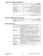


Traction and Reel Drive Systems
Item
Description
Transmission
Electric motor to transmission
Transmission drive uses spur gears
Traction Drive
Transmission to traction drive uses a series of spur gears
Differential
Spur gear planetary differential
Parking Brake
Band style (at differential shaft drive)
Traction Drum
Dual aluminium, 19.1 cm (7.5 inch) diameter
Cutting Reel Drive
Transmission reel output shaft with disconnect
and sliding coupler
Final reel drive has 2 pulleys with positive drive belt
Belt tension maintained by an idler
Controls, Wheels and Accessories
Item
Description
Transport Wheel (Optional) Tire
Pressure
83 to 103 kPa (12 to 15 PSI)
DPA Cutting Units
Frame construction:
Precision machined die cast aluminum crossmember with 2 bolt-on
die-cast aluminum side plates.
Reel construction:
Reels are 53.3 cm (21 inches) in length and 12.7 cm (5 inch) in
diameter. High strength, low alloy steel blades are thru hardened
and impact resistant. Reels are available in 8, 11 and 14 blade
configurations.
Height-of-cut:
Cutting height is adjusted on the front roller by two vertical screws.
Standard bench height of cut range is 1.6 to 16 mm (0.062 to 0.625
inch) depending on type of bedknife installed. An optional high
height-of-cut kit is available to obtain a cut range of 11.1 to 30 mm
(0.438 to 1.2 inch). Effective HOC may vary depending on turf
conditions, type of bedknife, rollers, attachments installed and rear
drum position.
Bedknife and bedbar:
Replaceable single edged Edgemax™ bedknife (solid tool steel
construction) is standard. Bedknife is fastened to the bedbar with
thirteen bedknife screws. A variety of optional bedknives are available.
Bedknife adjustment
Dual adjustment (one on each side of the bedbar) with 0.018 mm
(0.0007 inch) bedknife movement for each detent.
Rollers:
The front roller is a 6.3 cm (2.5 inches) diameter roller that is available
in full, wide spaced Wiehle and narrow spaced Wiehle configurations.
Grass shield:
Adjustable shield to improve grass discharge from reel in varying
moisture conditions.
Counterbalance
weight:
A cast iron weight mounted on left end of the cutting unit.
Greensmaster
®
e1021/e1026
Page 2–3
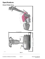
Specifications and Maintenance: Specifications
20246SL Rev A
Summary of Contents for 04831
Page 4: ...NOTES NOTES Page 4 Greensmaster e1021 e1026 20246SL Rev A ...
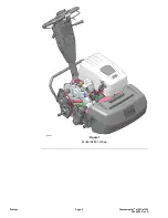
Page 6: ...g340650 Figure 1 Model 04831 shown Preface Page 6 Greensmaster e1021 e1026 20246SL Rev A ...
Page 14: ...Safety Safety and Instructional Decals Page 1 6 Greensmaster e1021 e1026 20246SL Rev A ...
Page 136: ...Electrical System Service and Repairs Page 5 56 Greensmaster e1021 e1026 20246SL Rev A ...
Page 216: ......


