


g032465
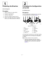
Figure 22
Right Drive Configuration
1.
Drive pulley
3.
Idler
2.
Belt
4.
Driven pulley
Ensure that any cutting units that use a left drive
configuration are set up correctly; refer to
.
g032697
Figure 23
Left Drive Configuration
1.
Drive pulley
3.
Idler
2.
Belt
4.
Driven pulley
10
Installing the Cover
Parts needed for this procedure:
1
Cover
3
Hex-socket screw (1/4 x 3/8 inch)
Procedure
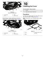
Use the 3 hex-socket screws (1/4 x 3/8 inch) to secure
the cover to the drive housing (
).
Note:
Position the cover so that the notch is at the
bottom.
g033565
Figure 24
1.
Cover
3.
Hex-socket screw (1/4 x
3/8 inch)
2.
Notch
11
Summary of Contents for 04650
Page 14: ...Notes...
Page 16: ......