Toro 04202 Greensmaster Flex 21 Operator'S Manual Download Page 4

Operation

Note:

Determine the left and right sides of the

machine from the normal operating position.

Adjusting the Rear Roller

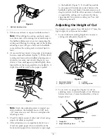
1. Adjust the rear roller brackets to the low or high

position depending on desired height of cut range
(Figure 3 and Figure 4).

Position the spacer above the side plate
mounting flange (factory setting) when height
of cut settings range from 1/16 to 1/4 inch (1.5
to 6.3 mm) (Figure 3).

Figure 3

1.

Spacer

3.

Roller bracket

2.

Side plate mounting flange

Position the spacer below the sideplate
mounting flange when height of cut settings
range from 1/8" to 1" (Figure 4).

Figure 4

1.

Sideplate mounting flange

3.

Roller bracket

2.

Spacer

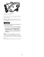
2. To adjust rear roller proceed as follows:

Raise rear of cutting unit and place a block
under bedknife.

Remove (2) nuts securing each roller bracket
and spacer to each sideplate mounting flange.

Lower roller and screws from sideplate
mounting flanges and spacers.

Place spacers onto screws on roller brackets.

Re-secure roller bracket and spacers to
underside of sideplate mounting flanges with
nuts previously removed.

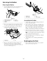
3. Verify that the bedknife to reel contact is correct.

Tip mower to expose front and rear rollers and
bedknife.

Note:

The position of the rear roller to the

reel is controlled by the machining tolerances
of the assembled components and paralleling is
not required. A limited amount of adjustment is
possible by setting the cutting unit on a surface
plate and loosening the sideplate mounting bolts
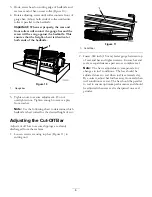
(Figure 5). Adjust and re-tighten bolts.

Figure 5

1.

Sideplate mounting bolts

Important:

Whenever the cutting unit has to

be tipped to expose bedknife/reel, prop up rear
of cutting unit to make sure nuts on back end
of bedbar adjusting screws are not resting on
work surface.

Adjusting the Bedknife to the
Reel

Bedknife to reel adjustment is accomplished by
loosening or tightening bedbar adjusting screws, located
on top of mower.

1. Position machine on a flat, level work surface.

2. Make sure reel contact is removed by turning bedbar

adjusting screws counterclockwise (Figure 6).

4

Summary of Contents for 04202 Greensmaster Flex 21

Page 1: ...s Model No 04202 Serial No 311000001 and Up Model No 04206 Serial No 311000001 and Up Model No 04207 Serial No 311000001 and Up Model No 04208 Serial No 311000001 and Up To register your product or download an Operator s Manual or Parts Catalog at no charge go to www Toro com Original Instructions EN ...

Page 2: ...omer Service and have the model and serial numbers of your product ready Figure 1 identifies the location of the model and serial numbers on the product Write the numbers in the space provided Figure 1 1 Location of the model and serial numbers Model No Serial No This manual identifies potential hazards and has safety messages identified by the safety alert symbol Figure 2 which signals a hazard t...

Page 3: ...e fitting clothing which could get caught in moving parts Always wear long pants and substantial shoes Wearing safety glasses safety shoes and a helmet is advisable and required by some local ordinances and insurance regulations Remove all debris or other objects that might be picked up and thrown by the cutting unit reel blades Keep all bystanders away from the working area If the cutting blades ...

Page 4: ...spacers onto screws on roller brackets Re secure roller bracket and spacers to underside of sideplate mounting flanges with nuts previously removed 3 Verify that the bedknife to reel contact is correct Tip mower to expose front and rear rollers and bedknife Note The position of the rear roller to the reel is controlled by the machining tolerances of the assembled components and paralleling is not ...

Page 5: ...overtighten the adjusting screws 5 Check for light contact at other end of reel using paper and adjust as required 6 After adjustment is accomplished check to see if reel can pinch paper when inserted from the front and cut paper when inserted at a right angle to the bedknife Figure 7 It should be possible to cut paper with minimum contact between the bedknife and the reel blades Should excessive ...

Page 6: ... following chart to determine which bedknife is best suited for the desired height of cut Adjusting the Cut Off Bar Adjust cut off bar to assure clippings are cleanly discharged from the reel area 1 Loosen screws securing top bar Figure 11 to cutting unit Figure 11 1 Cut off bar 2 Insert 060 inch 1 5 mm feeler gauge between top of reel and bar and tighten screws Ensure bar and reel are equal dista...

Page 7: ...nded Microcut Flex 21 0 062 0 125 inches 1 57 3 1 mm Less Aggressive 98 7261 Microcut Flex 18 0 062 0 125 inches 1 57 3 1 mm Standard 11 Blade 117 1530 EdgeMax Microcut Flex 18 0 062 0 125 inches 1 57 3 1 mm Standard 14 Blade 98 7260 Tournament Flex 18 0 125 0 250 inches 3 1 6 mm 117 1532 EdgeMax Tournament Flex 18 0 125 0 250 inches 3 1 6 mm Longer Wearing 110 2300 Extended Microcut Flex 18 0 062...

Page 8: ...re 12 for pulley locations Drive pulley number of teeth Driven pulley number of teeth 14 Blade Clip inch mm 11 Blade Clip inch mm 8 Blade Clip inch mm 27 standard 22 standard 0 112 2 9 0 143 3 6 0 197 5 0 22 22 0 138 3 5 0 176 4 5 0 241 6 1 22 27 0 172 4 4 0 219 5 6 0 301 7 7 The reel is shipped with one 27 tooth and one 22 tooth pulley To get a 16 inch 4 mm clip you must purchase a 22 tooth pulle...

Page 9: ... arms to traction unit frame tube Figure 14 Figure 14 1 Cutting unit pivot arms 3 Bolts 2 Traction unit frame tube 5 Rotate pivot arms forward Figure 14 and rest traction unit on restrained kickstand 6 Pull cutting unit forward about 2 inch 51 mm and then to the right to disengage the transmission coupling Figure 15 Figure 15 1 Transmission coupling 7 Reverse procedure to install cutting unit Note...

Page 10: ...ar bolt 3 Nut 2 Steel washer 4 Nylon washer Assembling the Bedbar 1 Install bedbar positioning mounting ears between washer and bedbar adjuster 2 Secure bedbar to each side plate with bedbar bolts jam nuts on bolts and 8 washers A nylon washer is to be positioned on each side of side plate boss Place a steel washer outside each of the nylon washers Torque bolts to 240 320 in lb 27 36 N m 3 Tighten...

Page 11: ...al injury Stay away from the reel while backlapping Never use a short handled paint brush for backlapping Part No 29 9100 Handle assembly complete or individual parts are available from your local Authorized Toro Distributor Note For a better cutting edge run a file across the front face of the bedknife when the lapping operation is completed This will remove any burrs or rough edges that may have...

Page 12: ...painted surfaces scratched decals or windows etc Parts Parts scheduled for replacement as required maintenance are warranted for the period of time up to the scheduled replacement time for that part Parts replaced under this warranty are covered for the duration of the original product warranty and become the property of Toro Toro will make the final decision whether to repair any existing part or...

Reviews: