


g017590
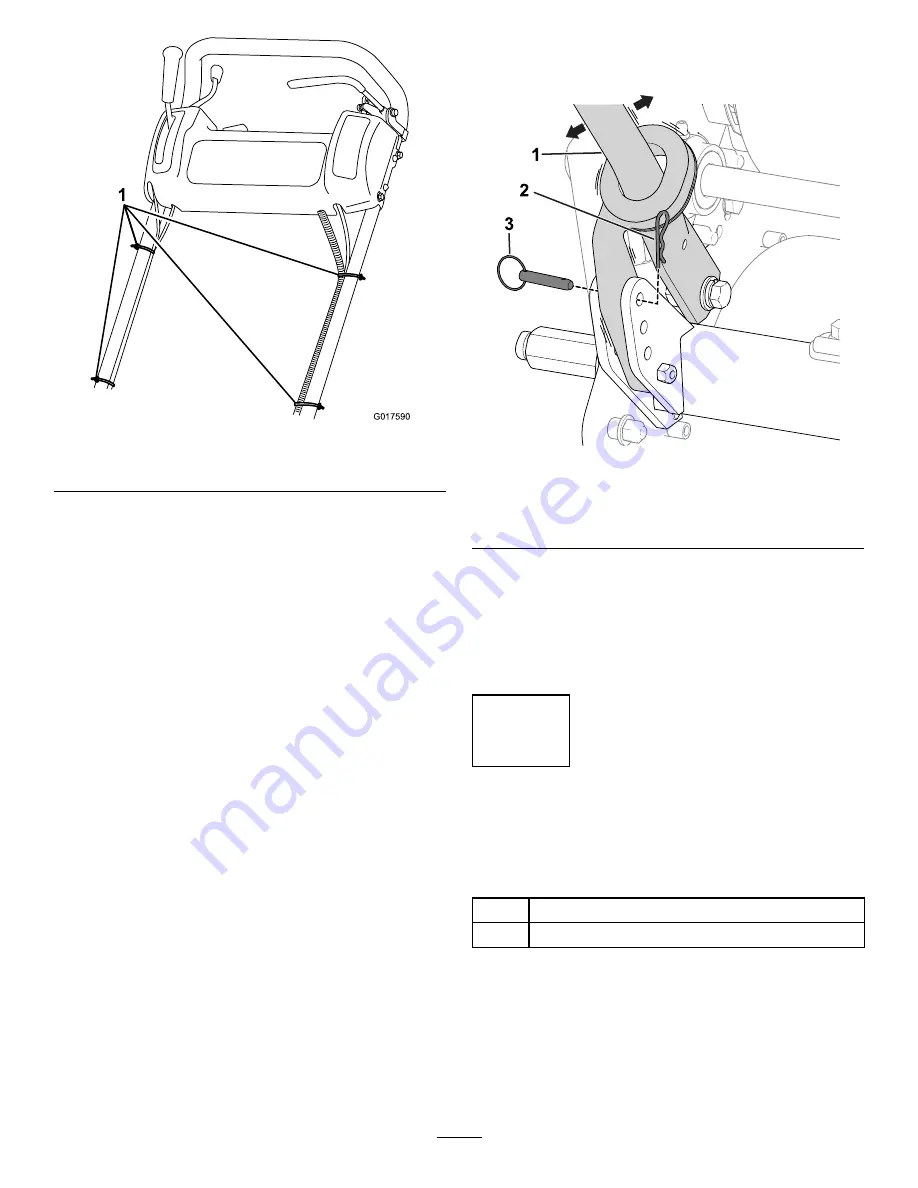
Figure 5
1.
Cable ties
Adjusting the Handle
Refer to
for this procedure.
g240512
Figure 6
1.
Handle
3.
Ring pin
2.
Hairpin cotter
1.
Remove the hairpin cotters from the ring pins on
each side of the machine.
2.
While supporting the handle, remove the ring
pins from each side and raise or lower the
handle to the desired operating position.
3.
Install the ring pins and hairpin cotters.
2
Installing the Kickstand
Models 04054 and 04056 Only
Parts needed for this procedure:
1
Kickstand assembly
1
Spring
Procedure
Note:
The machine is shipped with the fasteners
loosely installed on the kickstand assembly.
1.
On Model 04056 only
, connect the spring stud
to the right-hand side of the kickstand (
)
with the bolt, washer, and flange nut provided.
9


