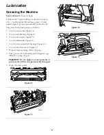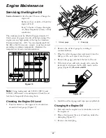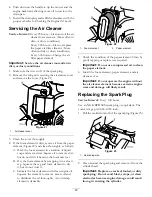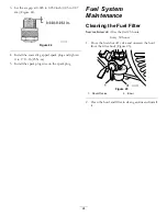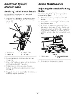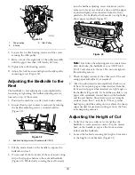
Figure 41
1.
Height-of-cut arm
3.
Locknut
2.
Height-of-cut bracket
4.
Adjusting screw
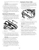
3. Loosen the nut on the gauge bar (Figure 42) and set
the adjusting screw to the desired height-of-cut. The
distance between the bottom of the screw head and
the face of the bar is the height-of-cut.
Figure 42
1.
Gauge bar
3.
Nut
2.
Height adjusting screw
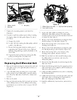
4. Hook the screw head on the cutting edge of the
bedknife and rest the rear end of the bar on the rear
roller (Figure 43).
Figure 43
5. Rotate the adjusting screw until the roller contacts
the front of the gauge bar.
6. Adjust both ends of the roller until the entire roller
is parallel to the bedknife.
Important:
When set properly, the rear and
front rollers will contact the gauge bar and the
screw will be snug against the bedknife. This
ensures the height-of-cut is identical at both
ends of the bedknife.
7. Tighten nuts to lock the adjustment.
Important:
To avoid scalping on undulating
turf, ensure that the roller supports are
positioned rearward (the roller closer to the reel).
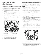
Note:
The front roller can be put in three different
positions (Figure 44), depending on the application
and needs of the user.
•
Use the front position when a groomer is
installed.
•
Use the middle position without a groomer.
•
Use the third position in extremely undulating
turf conditions.
Figure 44
Adjusting the Grass Shield
Height
Adjust the shield to ensure proper grass clipping
discharge into the basket.
1. Measure the distance from top of the front support
rod to the front lip of the shield at each end of the
cutting unit (Figure 45).
Figure 45
1.
Support rod
2.
Shield
2. The height of the shield from the support rod for
normal cutting conditions should be 4 inches (10
31

