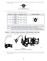
3.
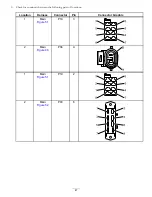
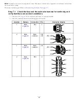
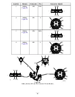
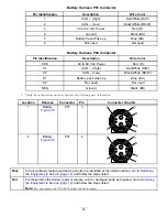
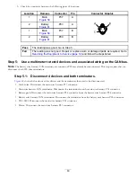
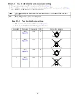
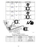
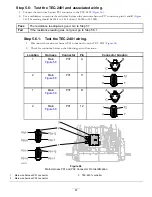
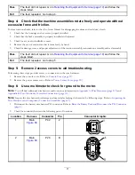
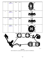
Check for continuity between the following pairs of locations:
Location
Harness
Connector
Pin
Connector Graphic
1
Main
P37
A
2
Battery
P03
A
1
Main
P37
B
2
Battery
P03
B
B
C
A
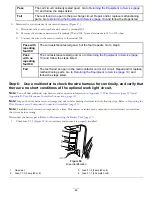
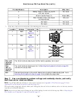
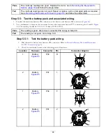
Pass
The reading was good. Go to Step
.
Fail
The reading was not good. Repair or replace worn or damaged parts as required. Go to
Returning the Equipment to Service (page 19)
and follow the steps listed.
Step 5:
Use a multimeter to test 4 devices and associated wiring on the CAN bus.
Note:
The battery wire harness CAN terminator at connector P03 may already be disconnected. This step requires that you
disconnect both 120-ohm terminators.
Step 5.1:
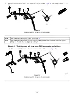
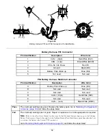
Disconnect 4 devices and both terminators.
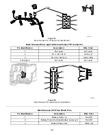
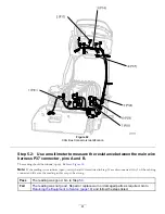
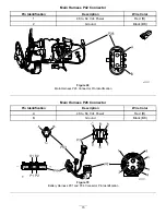
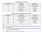
shows the locations of the devices and the terminators that need to be disconnected.
•
InfoCenter: Disconnect the main wire harness P17 connector.
•
Main wire harness CAN terminator: Disconnect the terminator from the main wire harness P14 connector.
•
Battery pack: Disconnect the main wire harness P34 connector from the battery wire harness P34 connector.
•
Battery wire harness CAN terminator: Disconnect the terminator from the battery wire harness P03 connector.
•
TEC-2401: Disconnect the main wire harness P01 connector.
•
Motor: Disconnect the main wire harness P41 connector.
60

