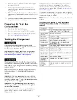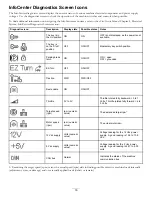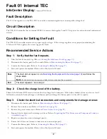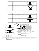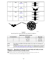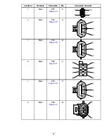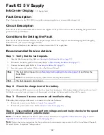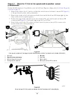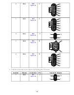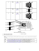
If any of the 3 components function correctly, the 12 Vdc supply is working properly and you should focus on a non-operational
component and/or circuit.
Note:
For information on how to test the EZ-Turn sensor, refer to the
eFlex Service Manual
for the machine.
Step 4.1:
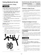
Test the InfoCenter wire harness connector for 12 Vdc.
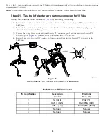
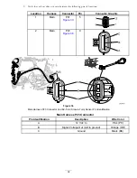
Test the InfoCenter wire harness connector (
) by performing the following:
1.
Rotate the key switch to the O
FF
position, and then disconnect the main wire harness P17 connector from the
InfoCenter.
2.
Rotate the key switch to the S
TART
position and hold it there until the InfoCenter LCD display lights up, then
release the key switch to the R
UN
position.
3.
Measure the voltage between the main wire harness P17 connector, pin 2, and the main wire harness P04
connector, pin B (
). The range for a good reading is 10.5 to 13.8 Vdc.
4.
Rotate the key switch to the O
FF
position, and then connect the main wire harness P17 connector to the
InfoCenter.
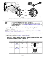
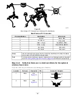
Figure 29
Main Wire Harness P17 Connector and InfoCenter Pin Identification
Main Harness P17 Connector
Pin Identification
Description
Wire Color
1
Ground
Black (BK)
2
12 Vdc In
Pink (PK)
3
CAN + (High)
Red/White (R/W)
4
CAN – (Low)
Black/White (BK/W)
5
Not used
Not used
6
Not used
Not used
24

