3.
Finish the cleaning with a fiber bristle brush dipped
in isopropyl alcohol.
4.
Gently wipe off the clean pins, terminals, and
components with a lint-free cloth dampened with
isopropyl alcohol.
5.
When available, dry the components with dry, oil-free
compressed air (maximum air pressure 20 psig/137.895
kPa).
6.
Ensure all connectors and components are clean and
dry prior to reassembly and testing.
Preparing to Test the
Components
1.
Park the machine on a level surface.
2.
Move the traction lever to the N
EUTRAL
position.
3.
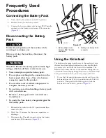
Move the kickstand into the J
ACK
S
TAND
position.
Refer to
Using the Kickstand (page 17)
.
Testing the Component
CAUTION
Performing continuity testing on electrical
components with the battery pack connected can
lead to severe electrical shock.
Disconnect the battery pack from the machine
before testing electrical components. Refer to
Disconnecting the Battery Pack (page 17)
.
CAUTION
Wearing jewelry while troubleshooting or testing
the machine can be dangerous. Jewelry can cause a
short circuit or get caught on the machine, causing
serious injury.
Remove all jewelry, especially rings and watches,
before doing any electrical troubleshooting or
testing.
Important:
The Greensmaster eFlex uses a 53-Vdc
battery-based electrical system. Actual measurements
of voltage will vary from 42 to 64 Vdc, depending on the
charge level of the battery pack.
Important:
The machine frame is not used as an
electrical ground. Ground is distributed through the
machine wire harnesses.
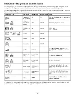
Some components can be tested through the InfoCenter
display. Refer to the
eFlex Service Manual
, Chapter 4,
Diagnostics Screen.
If diagnosis using the InfoCenter is not possible, remove
power from the machine by turning the key switch to
the O
FF
position, removing the key from the switch, and
disconnecting the battery pack. Refer to
Battery Pack (page 17)
.
For accurate resistance and/or continuity checks, electrically
isolate the component being tested by disconnecting all wiring
or removing it from the circuit).
Note:
Refer to the
eFlex Service Manual
Chapter 4, Electrical
System.
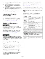
Components Covered in the Component
Testing Procedures in the eFlex Service
Manual
Component
Detail
Fuse block
Fuse F1-1 (30 amp/80 volt), fuse F1-2 (3
amp/80 volt), fuse F1-3 (3 amp/80 volt)
Lithium battery
pack fuse
58V fuse replacement
Key switch
Key switch testing
Parking brake
latch switch
Parking brake latch switch operation,
testing, and removal/installation
Traction switch
Traction switch operation, testing, and
removal/installation
Reel-engage
switch
Reel-engage switch operation, testing, and
removal/installation
EZ-Turn switch
EZ-Turn switch testing
EZ-Turn sensor
EZ-Turn sensor testing
Speed-control
potentiometer
Speed-control potentiometer operation and
testing
Main contactor
Main contactor testing
Toro Electronic
Controller
(TEC-2401)
Toro Electronic Controller information
CAN-Bus
termination
resistor
CAN-Bus termination resistor and resistor
testing
15


