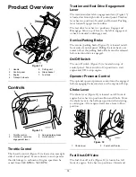
Figure 6
1.
Left handle end
5.
Large bolt (M8–1.25 x
100)
2.
Locknut (M8–1.25)
6.
Spring
3.
Small spacer
7.
Large spacer
4.
Washer (M8)
8.
Ssmall bolt (M8–1.25 x
030)
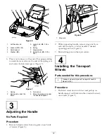
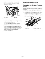
6. Place a nut runner over the end of the spring pointing
towards the rear and move the end of the spring over
and under the kickstand spacer (Figure 7).
Figure 7
1.
Spring
3.
Nut runner
2.
Spring end under the
frame
4.
Move the spring end under
the kickstand spacer.
3
Adjusting the Handle
No Parts Required
Procedure
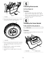
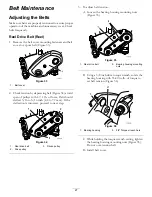
1. Remove hairpin cotters from ring pins on each side
of mower (Figure 8).
Figure 8
1.
Ring pins
2. While supporting handle, remove ring pins from
each side and raise or lower handle to desired
operating position (Figure 8).
3. Reinstall ring pins and hair pin cotters.
4
Installing the Transport
Wheels
Parts needed for this procedure:
2
Transport wheels (Optional Transport Wheel Kit,
Model 04123)
Procedure
1. Push kick stand down with foot and pull up on
handle support until kick stand has rotated forward,
over center (Figure 9).
12
Summary of Contents for 04030
Page 39: ...Notes 39 ...


