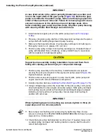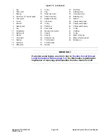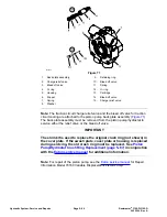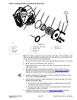
Removing the Hydraulic Tank (
1. Park the machine on a level surface. Lower cutting units, stop engine and
engage parking brake. Remove key from the key switch.
2. Read the
General Precautions for Removing and Installing Hydraulic System
Components (page 5–62)
.
3. To prevent contamination of hydraulic system during hydraulic tank removal,
thoroughly clean exterior of tank.
4. To allow draining of hydraulic tank, disconnect the suction hose from the tank
strainer in the bottom of the tank. Drain tank into a suitable container.
5. Disconnect hydraulic lines from tank and put caps or plugs on open hydraulic
lines and fittings. Label disconnected hydraulic lines for proper assembly.
6. Remove tank strainer from hydraulic tank. Discard O−ring from strainer.
7. Remove four (4) flange head bolts, flat washers and grommets that secure
hydraulic tank to machine. Remove hydraulic tank from machine.
8. If fittings are to be removed from tank, mark fitting orientation to allow correct
assembly. Remove the fittings from tank and discard O−rings from fittings.
Hydraulic Tank Inspection
1. Clean the hydraulic tank and suction strainer with solvent.
2. Inspect the hydraulic tank for leaks, cracks or other damage.
Installing the Hydraulic Tank (
1. If the fittings were removed from hydraulic tank, lubricate and place new
O−rings onto fittings. Install fittings into tank openings using marks made
during the removal process to properly orientate fittings. Tighten fittings
(see
Installing the Hydraulic Fittings (SAE Straight Thread O-Ring Fittings)
(page 5–8)
.
2. Position hydraulic tank to machine. Apply anti−seize lubricant or equivalent
to the four (4) flange head bolts that secure the hydraulic tank. Secure the
tank to frame with flange head bolts, flat washers and grommets. Torque the
bolts from
3.4 to 6.8 N·m (30 to 60 in−lb)
.
3. Lubricate and install the new O−ring on suction strainer.
4. Thread suction strainer into hydraulic tank. Using a wrench, turn suction
strainer into tank port at least 1−1/2 to 2 full turns beyond finger tight.
5. Remove caps and plugs from fittings and hydraulic lines. Properly connect
hydraulic lines to hydraulic tank (see
Installing Hydraulic Hoses and Tubes
(O-Ring Face Seal Fittings) (page 5–6)
).
6. Fill hydraulic tank with new hydraulic fluid.
7. Operate machine. Check hydraulic fluid level and adjust if necessary. Check
hydraulic components for leaks. Tighten any loose connections.
Hydraulic System: Service and Repairs
Page 5–72
Reelmaster
®
3100-D/3105-D
20252SL Rev A
Summary of Contents for 03200 Reelmaster 3100-D
Page 4: ...NOTES NOTES Page 4 Reelmaster 3100 D 3105 D 20252SL Rev A ...
Page 6: ...g341979 Figure 1 Preface Page 6 Reelmaster 3100 D 3105 D 20252SL Rev A ...
Page 10: ...Preface Page 10 Reelmaster 3100 D 3105 D 20252SL Rev A ...
Page 20: ...Safety Safety and Instructional Decals Page 1 10 Reelmaster 3100 D 3105 D 20252SL Rev A ...
Page 44: ...Specifications and Maintenance Special Tools Page 2 24 Reelmaster 3100 D 3105 D 20252SL Rev A ...
Page 224: ...Hydraulic System Service and Repairs Page 5 148 Reelmaster 3100 D 3105 D 20252SL Rev A ...
Page 385: ......


