background image

C242

SHINDAIWA OWNER’S/OPERATOR’S MANUAL
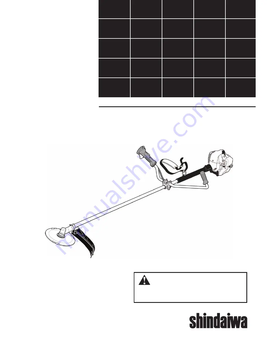
C242 BRUSHCUTTER

WARNING!

Minimize the risk of injury to yourself and others! Read this 
manual and familiarize yourself with the contents. Always 
wear eye and hearing protection when operating this unit.

Part Number 81359 Rev 8/06

Summary of Contents for 81359

Page 1: ... MANUAL C242 BRUSHCUTTER WARNING Minimize the risk of injury to yourself and others Read this manual and familiarize yourself with the contents Always wear eye and hearing protection when operating this unit Part Number 81359 Rev 8 06 ...

Page 2: ...nt serious bodily injury Work Safely Shindaiwa trimmers operate at very high speeds and can do serious damage or injury if they are misused or abused Neverallowapersonwithouttrainingor instructiontooperatethis unit Stay Alert You must be physically and mentally fit to operate this unit safely Safety Instructions WARNING WARNING Never operate power equipment of any kind if you are tired or if you a...

Page 3: ...w blade should bind fast in a cut shut off the engine immediately Push the branch or tree to ease the bind and free the blade Safety Instructions The Properly Equipped Operator Always operate with both hands firmly gripping the unit Wear close fitting clothing to pro tect legs and arms Gloves offer added protection and are strongly recommended Do not wear clothing or jewelry that could get caught ...

Page 4: ...use extreme cau tion to avoid contacting such items with the cutting attachment Be constantly alert for objects and debris that could be thrown either from the rotating cutting attachment or bounced from a hard surface Reduce the risk of bystanders being struck by flying debris Make sure no one is within 50 feet 15 meters that s about 16 paces of an operating attachment Figure 2 50 FEET C242 Safet...

Page 5: ... centrifugal clutch w bevel gear EPA Emission Compliance Period Category A The EPA emission compliance referred to on the emission compliance label located on the engine indicates the number of operating hours for which the engine has been shown to meet Federal emission requirements Category C 50 hours Moderate B 125 hours Intermediate and A 300 hours Extended n Engine Outer tube assembly n Handle...

Page 6: ...bracket over the outer tube and loosely install the four socket head screws See Figure 5 3 Tighten the four socket head cap screws to secure the cutting attachment shield 4 Re tighten clamp screw and retaining nut Assembly Sub Shield C242 when trimmer head is in use 1 Attach the shield extension to the cutting attachment shield See figure 6 WARNING NEVER use this machine without sub shield when us...

Page 7: ...knut 5 Reinstall the air cleaner cover Handle Bar C242 Assembly Continued Figure 10 Lock Nut Cable Adjuster Install the handlebar 1 Use the 4 mm hex wrench to remove the lower cap retaining screws from the handlebar bracket Remove the cap from the bracket See Figure 7 2 Position the handle on the outer tube forward of Handle Positioning Label as shown in Figure 7 Reassemble the lower cap to the ha...

Page 8: ... See Figure 11A 2 Using the combination spark plug screwdriver wrench remove the shaft bolt and bolt guard See Figure 11A NOTE Make sure holder B is installed on the gear case with the splined hole engaging the gear case shaft 3 Using the hex wrench to secure Holder A install and hand tighten the trimmer head counter clockwise to install See Figure 11B 5 Remove the hex wrench from the gear case an...

Page 9: ...e The blade mounting hole must be centered over the raised boss on blade holder A IMPORTANT Both holders must be flat against the surface of the blade 3 Install blade holder B on the output shaft See Figure 13 4 Install the bolt guard and then the blade retaining bolt Using the combination spark plug wrench screwdriver tighten the bolt firmly in a counter clockwise direction The holder B must fit ...

Page 10: ...enated gaso line may cause increased operating temperatures Under certain condi tions alcohol based gasoline may also reduce the lubricating qualities of some 2 cycle mixing oils Never use any type of gasoline containing more than 10 alcohol by volume Generic oils and some outboard oils may not be intend ed for use in high performance 2 cycle engines and should never be used in your Shindaiwa engi...

Page 11: ...hen the engine starts slowly move the choke lever to the OPEN position See Figure 18 If the engine stops after the initial start close the choke and restart Idle the engine briefly before stopping about 2 minutes then slide the ignition switch to the O Engine OFF position Stopping the Engine Adjusting Engine Idle Figure 19 Figure 20 The engine must return to idle speed whenever the throttle lever ...

Page 12: ...ure clutch failure Do not make modifications to this unit with out written approval from Shindaiwa Inc ALWAYS make sure the cutting attach ment is properly installed and firmly tight ened before operation NEVER use a cracked or warped cutting attachment replace it with a serviceable one ALWAYS make sure the cutting attach ment fits properly into the appropriate attachment holder If a properly inst...

Page 13: ...ation When operating a C242 with a blade make sure both the handle and shoulder strap are adjusted to the size of the operator us ing the unit Engine Operating Speeds Operate the unit at full throttle while cut ting Best fuel efficiency is obtained by releasing the throttle when swinging back after a cut n To prevent possible engine damage do not allow the brushcutter to run at high speeds without...

Page 14: ...e Figure 26 Clean or replace as necessary To clean element wash it thoroughly in soap and water Let it dry before reinstalling the element CAUTION Do not operate the unit if the air cleaner or element is damaged or if the element is wet Figure 26 n Carefully remove any accumulation of dirt or debris from the muffler or the fuel tank Dirt build up in these areas could cause engine overheating induc...

Page 15: ...n be dam aged easily Every 10 to 15 hours of operation Remove and clean the spark plug Adjust the spark plug electrode gap to 0 024 0 028 inch 0 6 0 7 mm If the spark plug must be replaced use only an NGK BPMR6A or equivalent resistor type spark plug of the correct heat range See Figure 27 CAUTION Before removing the spark plug clean the area around the plug to prevent dirt and debris from getting...

Page 16: ...er screen and cover to the muffler See Figure 30 4 Remove the screen and clean it with a stiff bristle brush 5 With a 4 mm hex wrench remove the 3 muffler bolts and the muffler See Figure 30 6 Inspect the cylinder exhaust port for any carbon buildup 7 Gently tap the muffler on a wood surface to dislodge any loose carbon Engine Cover Screws IMPORTANT If you note excessive carbon buildup consult wit...

Page 17: ...r extended periods can cause hard starting and could also lead to increased service and maintenance cost Blade Sharpening When the cutting edges of the blade be come dull they can be resharpened with a few strokes of a file In order to keep the blade in balance all cutting edges must be sharpened equally Shindaiwa Tornado Blade To sharpen the cutters on a Shindaiwa Tor nado Blade use a 7 32 inch r...

Page 18: ... the plug to 0 024 0 028 inch 0 6 0 7 mm Restart Replace the plug with an NGK BPMR6A or equivalent resistor type spark plug of the correct heat range Set spark plug electrode gap to 0 024 0 028 inch 0 6 0 7 mm YES What To Check Possible Cause Remedy LOW POWER OUTPUT Is the engine overheating Operator is overworking the unit Carburetor mixture is too lean Improper fuel ratio Fan fan cover cylinder ...

Page 19: ...pe spark plug of the correct range Idle engine until cool Cutting attachment rotates at idle Engine idle too high Broken clutch spring or worn clutch spring boss Loose attachment holder Engine will not idle down Engine idle set too high Engine has an air leak Clean the air filter Replace the fuel filter Consult with an authorized servicing dealer Adjust 3 000 250 RPM min 1 Set Idle 3 000 250 RPM m...

Page 20: ...lude certain related hoses and connectors Emission System Warranty Statement Owners Warranty Responsibilities As the small off road engine owner you are responsible for the performance of the required maintenance listed in this owners manual Shindaiwa Corporation recommends that you retain all receipts covering maintenance on your small off road engine but Shindaiwa Corporation cannot deny warrant...

Page 21: ...almente equipado El sistema de control de emisión de su motor Shindaiwa puede también incluir ciertas mangueras y conexiones particulares Declaración de Garantía del Sistema de Emisión Responsabilidades de Garantía del Propietario Como propietario del motor pequeño no para el uso en automóviles es usted responsable por el rendimiento del manten imiento requerido y mencionado en este manual del pro...

Page 22: ...correcta NGK BPMR6A o su equivalente con resistencia al calor correcta Marcha mínima hasta que enfríe El accesorio de corte gira con el motor en marcha mínima Marcha mínima ajustada muy alta Resorte del embrague está quebrado o el resorte patrón del embrague está gastado El soporte del accesorio está flojo Fije la marcha mínima 3 000 rpm 250 rpm min 1 Cambie los resortes zapatas como sea necesario...

Page 23: ... mising oil proporción 50 1 Combustible incorrecto rancio contaminado o mezcla incorrecta Consulte con su dirtribuidor autorizado Sobrecalentamiento Combustible inadecuado Depósitos de carbón en la cámara de combustión Se está sobrecalentando el motor El operador esta sobre trabajando la máquina La mezcla del carburador es muy pobre Proporción de combustible inapropiada Ventilador tapa del ventila...

Page 24: ...ble deje de pasar 2 Arranque y mantenga prendido el motor hasta que pare de funcionar 3 Repita los pasos 1 y 2 hasta que el motor ya no arranque PRECAUCIÓN Gasolina almacenada en el carbura dor por periódos largos puede causar un arranque duro y puede conducir a un aumento en costo de servicio y mantenimiento Afilado de Discos Cuando los bordes de la cuchilla pierdan su filo pueden ser afilados rá...

Page 25: ...on un cepillo de cerdas gruesas 5 Con una llave hexagonal de 3 mm retire los pernos del silenciador y el silencia dor Consulte la figura 30 6 Inspeccione el escape del cilindro en busca de acumulación de carbón 7 Suavemente golpee el silenciador sobre una superficie de madera para deshac erse de cualquier carbón suelto IMPORTANTE Si nota acumulación excesiva de carbón consulte con su centro de ser...

Page 26: ...ria de combustible con la punta del gancho de alambre pués esta línea es delicada y se puede dañar fácilmente Cada 10 ó 15 horas de oper ación Retire y limpie la bujía Ajuste la distancia del electrodo a 0 024 0 28 pulgadas 0 6 0 7 mm Si la bujía necesita ser reemplazada use solamente una bujía NGK CMR5H o una bujía equivalente con resistencia al calor correcta Consulte la figura 39 PRECAUCIÓN Ant...

Page 27: ... la figura 29 Limpie o reemplace como sea necesario Para la var el elemento Lavelo meticulosamente con agua y jabón Deje que seque antes de reinstalarlo PRECAUCIÓN No opere esta máquina si el filtro de aire está sucio dañado o si está húmedo n Cuidadosamente retire cualquier acumulación de suciedad o despojo del silenciador y del tanque de combustible La acumulación de suciedad en dichas áreas pue...

Page 28: ...e el mango y la correa de hombro estén ajustados a la talla del operador que usa la unidad Velocidades de Operación del Motor Opere el motor a máxima potencia mientras corte Para mayor eficiencia de combustible suelte el acelerador cuando voltee de regreso después de un corte n Para evitar posibles daños al motor no permita que la desmalezadora funcione a altas velocidades sin carga n Evite operar...

Page 29: ...o del soporte Si un cabezal propiamente instalado vibra reemplácelo por uno nuevo y pruebe SIEMPRE pare el motor inmediatamente y revise en busca de daños si golpea un objeto extraño o si la unidad se enreda No opere con equipo dañado o quebrado NUNCA permita que el motor funcione a altas revoluciones sin carga De lo contrario podría dañar el motor NUNCA use la máquina con sujetadores o soportes d...

Page 30: ... cebador a la posición OPEN abierto Consulte la figura 16 Si el motor para después del arranque inicial cierre la palanca del cebador y vuelva arrancar Figura 20 Abierto Ponga el motor en marcha mínima por dos o tres minutos antes de apagarlo luego deslice el interruptor de ignición a la posición O motor apagado Parada del Motor Ajuste de Marcha Mínima del Motor Figura 21 Figura 22 Tornillo de mar...

Page 31: ...Nunca use ningún combustible que contenga más de 10 de alcohol por volumén Aceites genéricos y algunos aceites para motores fuera de borda pueda que no sean para el uso en motores de dos ciclos de alto rendimiento y no deben ser usados en su motor Shindaiwa n Use solamente gasolina fresca limpia y sin plomo con índice de octanaje de 87 o superior n Mezcle todo el combustible con aceite de mezclar ...

Page 32: ... encajar en forma plana contra el borde del sujetador La muesca de montaje del disco debe estar centrada sobre el patrón elevado en el sujetador de disco A ADVERTENCIA Soporte B debe quedar alineado con la cuchilla y las tiras enganchadas al eje La C242 debe estar ahora completamente ensamblada y lista para ser usada con una cuchilla IMPORTANTE El reborde en el sujetador B debe rodear completament...

Page 33: ... la llave combinación de bujía destornillador retire el perno de eje y el protector de perno Consulte la figura 10 NOTA Asegurese que el sujetador B es instalado en la caja de engranajes con la muesca ranurada encajada con el eje de la caja de engranajes 3 Usando la llave hexagonal para asegurar el Sujetador A instale y apriete con la mano el cabezal para instalar gire en di rección contraria a la...

Page 34: ...e Mango C242 Ensamblaje Continuación Figure 5A C242 Instale el mango tipo barra 1 Use la llave hexagonal de 4mm para retirar los tornillos de retencion de la abrazadera inferior del soporte delman go Separe la tapa de la abrazadera fijese en la posicion de los dos espacia dores de 2 a instalarse entre la abraza dera Consulte la figura 5 2 Posicione el mango sobre el tuboex terior detras de la calc...

Page 35: ...or e instale sin ajustar los cuatro tornillos de cabeza allen Consulte la figura 9 3 Apriete los cuatro tornillos de cabeza allen para asegurar el protector del accesorio de corte 4 Volver a apretar el tornillo de la abraza dera al igual que la tuerca Figura 9 Protector del accesorio de corte Tubo Exterior Tornillo de cabeza hexagonal Soporte Espaciador Tornillo de la abrazadera Espaciador Retén P...

Page 36: ...125 horas Intermedio y A 300 horas Extendido IMPORTANTE Los términos izquierda mano izquierda y LH derecha mano derecha y RH delantera y trasera indican direcciones desde el punto de vista del operador du rante la operación normal de este producto n Motor Tubo de montaje del la parte exterior n Mango y Acelerado completo n Protector del accesorio de corte n Accesorio de corte n Kit conteniendo el ...

Page 37: ...se extremo cuidado y evite tocarlos con el accesorio de corte Esté constantemente alerta de los objetos y despojos que puedan ser lanzados por el accesorio de corte o rebotados Reduzca el riesgo de que algún transeúnte sea golpeado por un objeto volante Ase gurese de que nadie esté dentro de 50 píes 15 metros de distancia de un accesorio en operación Esto es aproxima damente 16 pasos Figura 2 50 p...

Page 38: ...condición Figura 1 Instrucciones de Seguridad ADVERTENCIA Use Buen Juicio SIEMPRE use protección para los ojos como escudo contra objetos lanzados NUNCA opere el motor cuando transporte la unidad NUNCA opere la unidad en el interior Cerciorese que siempre haya buena ventilación El humo o gases del escape del motor pueden causar serias lesiones o la muerte SIEMPRE mantenga su area de trabajo libre ...

Page 39: ...da por la palabra IMPORTANTE contiene información especial y significante Shindaiwa Inc se reserva el derecho de realizar cambios a sus productos sin previo aviso y sin la obligación de hacer modificaciones a máquinas fabricadas previamente Declaraciones de seguridad 2 Información de seguridad 2 Etiquetas de seguridad 4 Descripción del producto 5 Especificaciones 5 Ensamblaje 6 Ajustes 7 Combustib...

Page 40: ...smalezadora C242 Part Number 81359 Rev 8 06 ADVERTENCIA Disminuya el riesgo de sufrir lesiones o causar lesiones a otros Lea este manual y familiaricese con su contenido Siempre use protección para los ojos y oídos cuando opere esta máquina C242 ...

Reviews: