


g304544
Figure 9
1.
Bolt (M6 x 35 mm)
3.
Slope sensor
2.
Slope sensor mount
4.
Flange nut (M6)
13.
Connect the wire-harness connector labeled
P02 to the slope sensor.
14.
Use 2 bolts (M6 x 25 mm) and 2 flange nuts
(M6) to secure the slope sensor mount to the
electrical panel (
g304543
Figure 10
1.
Slope sensor mount
3.
Bolt (M6 x 25 mm)
2.
Flange nut (M6)
15.
Connect the kit-wire-harness connector labeled
P01 to one of the 6-pin sealed connectors
located below the relays on the electrical panel.
16.
Use cable ties to secure the wire harness away
from moving parts or pinch points.
17.
Install the slope-sensor decal adjacent to the
machine-stability decal on the storage-pod lid
(
g308336
Figure 11
1.
Machine-stability decal
2.
Slope-sensor decal
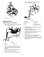
Installing the Kit
PLH800 Machines
1.
Remove the battery cover; refer to the electrical
system maintenance section of your
Operator’s
Manual
.
2.
Use 2 bolts (M6 x 35 mm) and 2 flange nuts
(M6) to secure the slope sensor on the mounting
plate in front of the battery (
).
g307264
Figure 12
1.
Battery
2.
Slope sensor
5


