background image

9

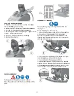
SYMBOLOGY ON THE MACHINE

Symbol denoting the solution valve.

Indicates the solution valve lever.

Symbol denoting the suction motor.

Indicates the switch of the suction motor.

Symbol denoting up-down of the squeegee.

Indicates the squeegee lever.

Symbol denoting the charge level of the 

batteries.

Indication of the maximum temperature of 

the detergent solution.

It is placed near the charging hole of the 

solution tank.

Symbol denoting the crossed bin. Indicates 

that at the end of its activity, the machine 

has to be disposed conforming to the laws 

in force.

SYMBOLOGY ON THE MANUAL

Indicates the switch of the brush motor.

Symbol denoting the brake lever of the 

emergency and parking brake.

Symbol denoting the selection switch of 

the driving speed.

Symbol denoting the hour meter.

Symbol denoting the brake.

Indicates the signal lamp of the brake on

.

Symbol denoting the open book. Indicates 

that the operator has to read the manual 

before the use of the machine.

Symbol denoting the open book.  For the 

good functioning of the battery charger, 

read the manual of the manufacturer.

Warning symbol.

Read carefully the sections marked with 

this symbol, for the security of both the 

operator and the machine.

Symbol that indicates the obligations 

of disconnecting the system from the 

batteries by disconnection the connector 

before working on the machine.

Symbol that indicates the obligation of 

wearing safety glasses.

Symbol that indicates the obligation of 

wearing safety gloves.

Symbol preceding important information 

about the correct use of the machine.

Symbol that indicates operations that have 

to be carried out only by qualified personnel.

Summary of Contents for OB 28/20

Page 1: ...ORT WORTH TX 76140 PHONE 800 VACUUMS FAX 817 551 0719 WWW TORNADOVAC COM Operations Maintenance Manual For Commercial Use Only Form No L9729AA 12 2018 Tornado Industries LLC All rights reserved OB 28...

Page 2: ...y Terms subject to change without notice 1 All Windshear Blowers Storm TV2SS Side and Downdraft Insulation Blowers CV 30 CV 38 CK14 1 PRO CK 14 1 BSE CK14 2 PRO SWM 31 9 CK LW13 1 CK LW 13 1 ROAM CV 3...

Page 3: ...3 NOTES...

Page 4: ...Recovery tank 13 Detergent solution tank 14 Starting of the machine 14 Forward movement 15 Speed adjustment 15 Working brake 15 Emergency brake 15 Adjustment of the base pressure 15 Overflow device 1...

Page 5: ...ter lift mbar 64 160 Type of drive automatic Movement speed max mph kph 2 2 8 3 2 4 5 Maximum gradient 10 Solution tank gal l 20 75 Reserve solution tank gal l 1 3 5 Recovery tank gal l 22 5 85 Machin...

Page 6: ...or use on a nominal 120 volt circuit and has a grounding plug that looks like the plug illustrated in sketch A Your new Tornado unit is a high quality precision made product All parts used in the manu...

Page 7: ...USE Do not use the machine on surfaces covered with inflammable liquids or dusts for example hydrocarbons ashes or soot In case of fire use a powder based fire extinguisher Do not use water Do not use...

Page 8: ...SWITCH SOLENOID VALVE LEGEND MACHINE 1 INSTRUMENT BOARD 2 KEY SWITCH 3 RECOVERY TANK COVER 4 RECOVERY TANK 5 PLUG EXHAUST HOSE 6 EXHAUST HOSE 7 DRIVE CONTROL LEVERS 8 SQUEEGEE LEVER 9 SOLUTION VALVE...

Page 9: ...switch of the driving speed Symbol denoting the hour meter Symbol denoting the brake Indicates the signal lamp of the brake on Symbol denoting the open book Indicates that the operator has to read th...

Page 10: ...battery compartment first of all make sure that the recovery tank 1 is empty by opening the cover 2 If the tank is full proceed as indicated under RECOVERY TANK CLEANING otherwise take off the squeeg...

Page 11: ...tank lifted see under paragraph BATTERY INSTALLATION AND SETTING OF THE BATTERY TYPE in BEFORE USE 3 Maintain the connection with the battery recharger until the indication of the end of charge is vis...

Page 12: ...indicating every 10 decrease When the charge level reaches 20 the display starts blinking indicating the end of the battery charge A few seconds after from the blinking of the four lines the base moto...

Page 13: ...djustment Once that the squeegee inclination has been adjusted it is necessary to fix this optimum condition making touch slightly the wheels onto the floor Release the wheels rotating counterclockwis...

Page 14: ...level hose that permits to see easily the solution quantity inside the tank both during the filling of the solution and during the working Screw down the solution tank cap STARTING OF THE MACHINE 1 Tu...

Page 15: ...ENT Two values of the maximum drive working speed in forward movement can be chosen Set the wanted speed through the speed selection switch 1 WORKING BRAKE To stop the machine during normal working si...

Page 16: ...ESERVE H2O ON THE DISPLAY When the indication H2O on the display appears this means that the detergent is getting low corresponding to 10 of the maximum capacity of the solution tank STOP OF THE MACHI...

Page 17: ...pad SQUEEGEE CLEANING Keeping the squeegee clean guarantees the best drying result For its cleaning it is necessary to 1 Take off the squeegee hose 4 from the coupling 2 Disassemble the squeegee from...

Page 18: ...se with a water jet To reassemble the hose repeat reverse the operations above mentioned Do not wash the hose that goes from the suction motor to the recovery tank CLEANING OF THE SOLUTION TANK 1 Brin...

Page 19: ...ctly plugged in 4 Verify that the switch 3 is on 5 Check that the red connector of the suction motor is correctly plugged in If the problem persists please contact the authorized technical assistance...

Page 20: ...ubbers are clean 2 Check the adjustment of the height and the inclination of the squeegee see section ADJUSTMENT OF THE SQUEEGEE in BEFORE USE 3 Check that the suction hose is correctly inserted in th...

Page 21: ...cleaning and maintenance equipment o Contacted by local dealer o Previous experience with Tornado products o Reputation Recommendation o Advertising o Direct mail o Website ____________ o Blog _______...

Reviews: