


10
BATTERIES DISPOSAL
It is compulsory to hand over exhausted bat-
teries, classified as dangerous waste, to an
authorized institution according to the current
laws.
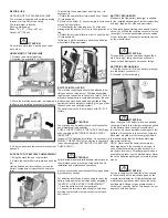
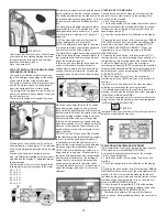
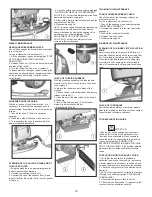
CONNECTION BATTERIES' CONNECTOR
AND SWITCHING ON OF THE MACHINE
Once that the battery recharging has been
completed:
1. Disconnect the connector of the battery
recharger from the battery connector (1).
2. Connect then the battery connector (1) to
the machine connector (2).
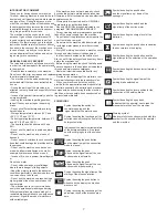
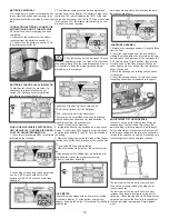
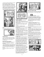
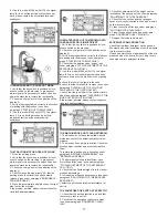
BATTERIES CHARGE LEVEL INDICATOR
To start any function of the machine, it is
necessary to rotate clockwise the key
switch (24). Rotating it counterclockwise
any function will be switched off.
WHEN THE MACHINE IS SWITCHED ON,
ON THE DISPLAY (1) APPEAR IN ORDER
THE FOLLOWING INFORMATION:
1. the version (for example A003) of software
installed on the machine.
2. the setting of the battery check card which
can be: GE 24 (check card set for GEL
batteries).or Pb 24 (check card set for lead
batteries).
3. The batteries charge level indicator is digital and
remains fixed on the display. The battery charge level
starts from 100, which indicates the 100% of the total
charge and decreases from 100 to 10. When the charge
level reaches 20%, the display starts blinking, so you
are about the end of working.
After few seconds of the indication 10% and
after this, the blinking of the four lines, all the functions
stop automatically. With the remaining charge it is any-
how possible to finish the drying operation before
proceeding to the recharge.
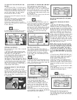
SETTING OF THE BATTERY CHECK CARD
The setting of the battery check card can be:
GE 24 (check card set for GEL batteries).
or
Pb 24 (check card set for lead batteries).
The machine, if not specified otherwise, is supplied
with the battery check card set for lead batteries. To
modify this setting, it is necessary to:
1. Switch off and on the machine.
2. Immediately after having switched on, when on the
display (1) the writing Pb24 appears, press simultane-
ously the push buttons (3) and (6) up to the blinking of
the writing.
3. When the writing begins to blink, take off the fingers
from the push buttons and press once the push button
(6).
4. The writing GE24 appears blinking.
5. When the writing stops to blink, the setting is modi-
fied.
For the passage of the setting from gel batteries into
lead batteries, repeat the procedure pressing
button (3) instead of button (6).
HOUR METER
The machine is equipped with an hour meter located
on the same display (1) of the battery charge level
indicator. Keeping the button (13) pressed, the first data
indicates the
working hours and after a few seconds the work-
ing minutes are shown.
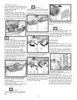
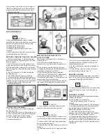
SQUEEGEE ASSEMBLY
1. Maintain the squeegee support (1) slightly lifted
from the floor.
2. Insert the threaded parts of the two knobs (4)
making them slide inside the two slots on the sup-
port placed on the upper part of the squeegee (2).
3. Put the washers (3) into position, they are two
for each knob, so that they are assembled one
under and the other on each of the two slots pres-
ent on the support.
4. Block the squeegee by rotating the two knobs
(4) clockwise.
5. Insert the squeegee hose (5) into its coupling,
respecting its position as indicated in the figure.
ADJUSTMENT OF THE SQUEEGEE
In order to have a perfect drying result through
the squeegee, the rear rubber must have the
lower bending uniformly adjusted in all its length.
For the adjustment, it is necessary to put oneself
in working condition and therefore the suction mo-
tor has to be switched on and the brushes have to
function together with the detergent solution.
The lower part of the rubber is too much bent
Take off the pressure rotating the wing nut (6)
counterclockwise.
The lower part of the rubber is not much bent
Increase the pressure rotating the wing nut (6)
clockwise. Check that the wheels which adjust the
height do not rest on the floor, in this case adjust
them as indicated in paragraph “Height adjust-
ment”.
Summary of Contents for BR 28/27
Page 2: ...2...
Page 3: ...3 NOTES...