6.1 CHOOSE A BLADE
Using the correct blade for the material is important to reduce
cost and to operate the bandsaw efficiently. Because there's a
wide variety of bandsaw blade types, you must first know the
specifications of the material you want to cut.
Choosing a blade depends on a number of different factors.
Use this section as a reference; for more information, see your
blade manufacturer's reference materials.
Note:
AF50 Autofeed Bandsaw blades are 93 in. × 3/4
in. × 0.35 in.
To choose a blade, determine the following:
1.
Teeth Per Inch (TPI)
Based on the size and shape of
the material, select the TPI. A high TPI cuts slower and
smoother, while a low TPI cuts faster and rougher. While
cutting, you must always have three teeth engaged with
the part.
Material Thickness Range
TPI Range
1/8 in. (6 mm) to 1/4 in.
10 to 14
1/4 in. to 1/2 in. (12 mm)
8 to 12
1/2 in. (12 mm) to 1 in.
6 to 10
1 in. to 2 in.
5 to 8
2 in. to 4 in.
3 to 4
4 in. to 7 in.
2 to 3
7 in. to 12 in.
1-2/5 to 2-1/2
2.
Tooth Form
Select the tooth form (the shape of the
cutting edge). The tooth form affects how the blade cuts
through the material.
3.
Tooth Set
Based on the required chip clearance, select
the tooth set (the angle at which the tooth is offset from
the blade). The particular tooth set is what carries the
chip away from the cut, and is important for surface
finish.
6.2 CHANGE A BLADE
The bandsaw arrives with a blade installed. To change the
blade, complete the following steps in the order listed:
6.2.2 Verify the Blade Installation
Note:
For simplicity, you must verify the blade
installation before you set the saw head down.
6.2.1 Install a New Blade
1. Put on work gloves, eye protection, and any other
appropriate personal protective equipment. We
recommend a long-sleeved shirt and long pants.
2. Power off the bandsaw and disconnect it from the main
air supply.
a. Push the Emergency Stop button on the operator
panel to lock it into the disabled position.
b. Turn the Main Disconnect switch to
OFF
.
Mains power is disconnected from the machine.
c. Disconnect the air line from your site from the input
port on the FRL Filter-Regulator-Lubricator.
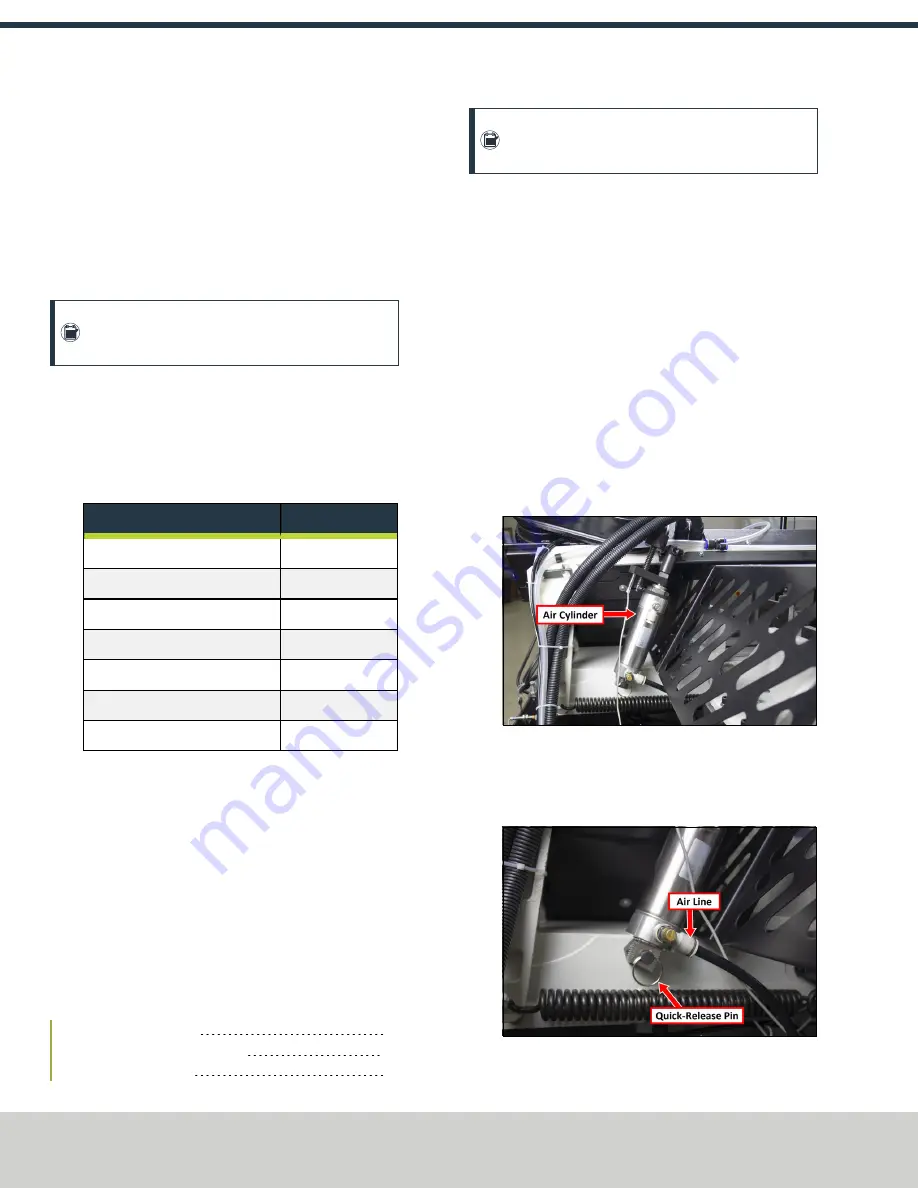
3. On the back of the machine, identify the air cylinder, as
shown in the following image.
Figure 6-1: Air cylinder on the back of the machine.
4. Turn the air line valve, which allows you to access the air
cylinder's quick-release pin, as shown in the following
image.
Figure 6-2: Quick-release pin on the air cylinder.
©Tormach® 2020
Specifications subject to change without notice.
Page 28
UM10538: Tormach AF50 Autofeed Bandsaw (Version 0320A)
For the most recent version, see tormach.com/support
6: BASIC OPERATIONS


