background image


NIRE-170-1-6 

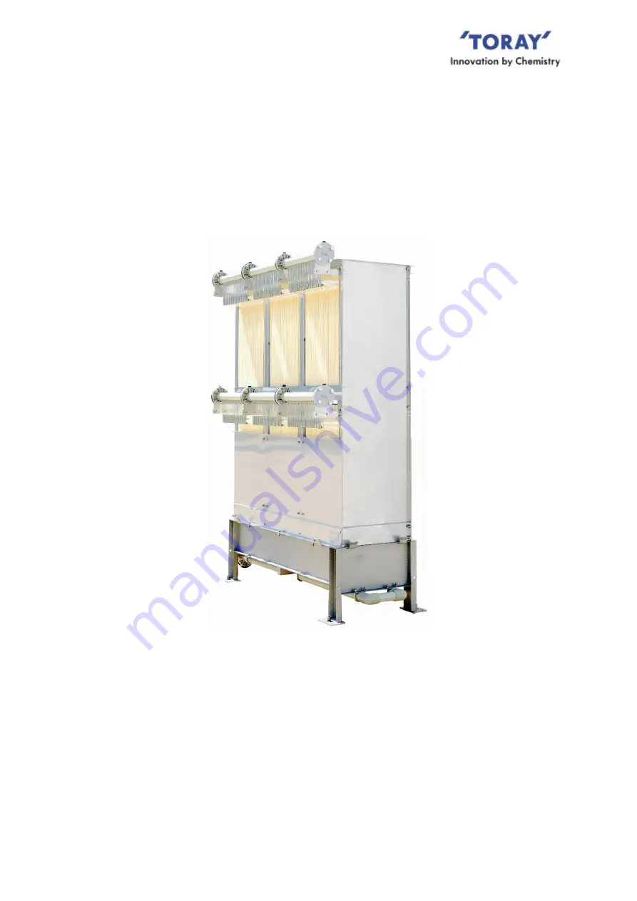
Submerged Membrane Module 

for MBR 

TORAY “MEMBRAY” 


“NHP210 Series” 

Instruction Manual 


Toray Industries, Inc. 

Water Treatment Division


1-1, Nihonbashi-muromachi 2-chome, Chuo-ku, Tokyo 103-8666 Japan 

Tel +81-3-3245-4542 

Fax +81-3-3245-4913 

URL www.toraywater.com 

Published:  August  2020


Summary of Contents for NHP210 Series

Page 1: ...r MBR TORAY MEMBRAY NHP210 Series Instruction Manual Toray Industries Inc Water Treatment Division 1 1 Nihonbashi muromachi 2 chome Chuo ku Tokyo 103 8666 Japan Tel 81 3 3245 4542 Fax 81 3 3245 4913 URL www toraywater com Published August 2020 ...

Page 2: ... Series Modules in Membrane Tank 18 4 Piping 21 V INSTALLATION OF NHP210 SERIES 24 1 Preparatory Procedure 24 2 Unloading lifting Products 24 3 Checking Products 25 4 Storage Products 25 5 Installation Products 26 VI START OF OPERATION 30 1 Clean Water Operation 30 2 Seeding Sludge Injection 31 3 Actual Filtration Operation 32 VII OPERATION CONTROL 33 1 Standard Operating Conditions 33 2 Operating...

Page 3: ...ed to indicate an imminent hazardous situation which if not avoided will result in serious injury or death This symbol is used to indicate a potentially hazardous situation which if not avoided can result in serious injury or death This symbol is used to indicate a potentially hazardous situation which if not avoided may result in injury or property damage DANGER WARNING CAUTION ...

Page 4: ...hould thoroughly read this manual to ensure stable operation 1 Features of MBR The process flow of the conventional activated sludge system CAS and MBR are shown in Fig I 1 and Fig I 2 respectively MBR provides the following advantages 1 Small Footprint Unlike CAS MBR separates sludge within aeration tank using membranes thus eliminate the space for preparing sedimentation tank Also with membrane ...

Page 5: ...rane elements are stacked at equal clearance each of which has flat sheet membrane on both sides Each element is connected via plastic tube to the filtrated water manifold The aeration block consists of coarse bubble air diffusers to supply scouring air see Fig I 3 This module is used submerged in sludge liquid The following shows the features of NHP210 Series Fig I 3 Components and appearance of ...

Page 6: ...ig I 5 This mechanism ensures stable filtration since the membrane does not easily admit of sludge adherence to its surface In addition thin membrane element makes it possible to have higher membrane packing density in the module similar to that of hollow fiber membrane and also to improve membrane cleaning efficiency thanks to vibration of elements by scouring air Fig I 4 Structure of Element Fig...

Page 7: ...gth and high chemical resistance 3 Membrane Pore Size Numerous small size pores are distributed evenly over the membrane surface with a sharp pore size distribution This structure gives an outstanding high treated water quality and excellent water permeability making the membrane highly resistant to clogging see Fig I 6 and Fig I 7 compared to other membranes The average pore size is 0 08 micron m...

Page 8: ...s of the membrane module via a scaffold or ladder Do not climb on the module structure Never step on the air diffuser manifold Use protective equipment to ensure the safety of workers Please wear the appropriate personal protective equipment e g work gloves in order not to cut hand on the edge of the module frame During transportation storage and installation take appropriate measures to protect N...

Page 9: ...d waste disposal company to perform the task When first filling the membrane tank with clean water make certain the air discharge valve is in the open position to assure any accumulated air is released After the tank is full with clean water close the air discharge valve Do not use ground water for the initial filling of the membrane tank Ground water may contain considerable concentrations of iro...

Page 10: ...ires air for normal metabolic processes However under these conditions the amount of air flow directed to the diffuser should be reduced to just the amount required to maintain sludge viability Once a filtrate tube has been removed or disconnected from either the element nozzle or filtrate manifold it should be replaced with a Toray approved replacement part Old filtrate tubes lose their elasticit...

Page 11: ...efore starting injecting chemical to elements confirm that the membrane tank liquid level is more than 500 mm above the top of the module Store chemicals in a dark cold place free from direct sunlight Use chemical storage tanks constructed of chemically compatible materials to prevent corrosion Never mix sodium hypochlorite with heavy metals or acids The resulting chemical reaction will generate t...

Page 12: ...ions mm Total width 480 Total height 800 Thickness 1 8 Weight kg Dry 0 25 Wet Reference 0 5 Main material Membrane PVDF and PET non woven fiber Nozzle PE Fig III 1 Element Appearance mm 2 Specifications of Filtrate Tube Assembly Table III 2 and Fig III 2 show the specifications and appearance of Tube Assembly Table III 2 Specifications of Filtrate Tube Assembly Material Thermoplastic polyether pol...

Page 13: ...ylene SS is available as option Connection Manifold ANSI 1 1 2 inch flange using M12 bolts nuts One flange per each deck 300S 2 pcs per module 600D 4 pcs per module Air diffuser ANSI 1 1 2 inch flange Using M12 bolts nuts Two flanges per Aeration block Operating range 3 Temperature 5 40 degree C pH 2 of liquid 5 10 MLSS Not higher than 18 000 mg L Trans membrane pressure Not higher than 20 kPa 200...

Page 14: ...Edition 1998 Section 2540D Total Suspended Solids Dried at 103 105 degree C or ISO 11923 3 Measuring method of NTU is complied with Standard Method of Examination of Water and Wastewater 20th Edition 1998 Section 2130 Turbidity or ISO 7027 Table III 5 Flow capacity Reference value Model name NHP210 300S NHP210 600D Filtration Flow m3 d 4 Sewage 20 150 40 300 Industrial wastewater 20 100 40 200 4 T...

Page 15: ... air scour should be suspended when the filtration process is stopped except for the following conditions 1 During normal membrane relaxation periods 2 During suspended filtration operation unless aeration is required for mixing or biological demand requirements For the latter the air flow should be reduced to minimum flow rates to prevent membrane damage During low wastewater supply period basica...

Page 16: ...ay result in large solids clogging or causing physical damage to the membrane surfaces In order to equalize BOD load and filtration flow capacity it is recommended that a buffer equalization tank be installed to help stabilize operation of the biological treatment and membrane filtration process 1 Gravity filtration configuration The filtration process can be accomplished by using elevation differ...

Page 17: ...gned high level the automatic shut off valve on the raw water influent line closes to stop raw water flow to the membrane tank In the gravity filtration mode air may accumulate in the filtrate water lines To prevent reduction or loss of suction the air in the filtrate line should be purged to atmosphere at least once per day The air purge nozzle should be installed at the highest position of the f...

Page 18: ...ation mode should be stopped As with the gravity filtration mode previously discussed should the membrane tank water level reach the upper designed liquid level set point the high level controller will close the raw water inlet control valve Since the liquid in the tank contains a significant amount of dissolved air some of that dissolved air will accumulate in the filtrate pump suction line It wo...

Page 19: ... of filtrate water When operating more than one NHP210 Series module simultaneously it is recommended that each train be fitted with its own discreet filtrate flow rate controller c Trans membrane pressure TMP measurement calculation For trans membrane pressure TMP determination the differential pressure in the filtrate line and water level needs to be measured and calculated This can be accomplis...

Page 20: ...o install at a minimum one air flow meter for each train f Suction pump A suction pump is required in the case of pump suction configuration To achieve an accurate designed filtrate flow rate the suction pump should be fitted with a VFD controller The use of a volute pump centrifugal pump or volumetric pump screw pump with self priming functions is recommended g Level sensor Level sensors are requ...

Page 21: ...portant to arrange the membrane modules with appropriate distances between each module to obtain an effective activated sludge circulation as well as not having excessive space around the modules which allows sludge sedimentation installing sludge agitation if necessary Fig IV 5a and Fig IV 5b illustrate a side view and a top view of the membrane tank containing three membrane modules It is requir...

Page 22: ...g aeration tank Contact Toray in the case the existing tank floor is not level If the existing tank floor is not level it is recommended that stands be installed as shown in Fig IV 6 Fig IV 6 Installation with Stands side view 2 Layout of Modules installed with Other Aeration Equipment In the case that the membrane modules are to be installed in a tank with other oxygen supplying aeration equipmen...

Page 23: ...nce between the modules and other aeration equipment in the case shown in Fig IV 8 Fig IV 8 Membrane Module Layout in Membrane Tank with Other Aeration Equipment top view Module Module Module Module Module Module Tank wall Oxygen Supplying Aeration Equipment Tank wall 2 W1 W1 W2 W2 W3 W3 Oxygen Supplying Aeration Equipment W1 W1 W2 W2 2 X W3 ...

Page 24: ...without putting stress to the air diffuser It is recommended that the air supply flange B be installed above the tank liquid level to facilitate removal should the module need to be lifted from the tank To facilitate cleaning of the air diffuser install branch pipes and valves as illustrated in Fig IV 9 it is recommended that these valves be located less than 500 mm above the liquid surface It is ...

Page 25: ...equired pump is above the membrane tank In both upward and downward piping the chemical injection valve and the air discharge valve should be installed on a pipe tee between the pipe from the filtrate water manifold to the filtrate water control valve These devices are necessary for chemical cleaning and are detailed in sections VIII 3 to VIII 6 It is advised that you prepare and attach riser pipe...

Page 26: ... some supports on the piping to reduce the load Please be sure to confirm that diameter of filtrate piping is suitable for the assumable maximum flow velocity at each point especially after aggregating filtrate flow from several manifolds such as header pipes 3 Maximum number of Modules in a single header A maximum number of 30 modules per filtrate header with subgroups of max 10 modules for aerat...

Page 27: ...ft crane or truck mounted hydraulic lift gate Inspect the NHP210 Series module for any damage inflicted during transport 1 You will receive two packages with the NHP210 Series module One is the element block complete with the prescribed number of membrane elements and the other box an aeration block 2 Do not lift the packages from overhead Always lift these packages from underneath using a forklif...

Page 28: ...licted during transport 3 Check to confirm that the protective covers remain in their correct position 4 Check to confirm that all the filtrate tubes are surely connecting elements and manifold 4 Storage Products Please store NHP210 Series indoors under lower than 40 degree C of the temperature If the NHP210 Series cannot be stored indoors due to prevailing construction site conditions try to mini...

Page 29: ...isions with other moving objects Be careful not to damage the rubber parts of air diffusers and element fixing brackets 5 Installation Products Check the followings before module installation 1 Make sure all necessary work in the membrane tank have been completed 2 Make sure the tank and all pipes have been thoroughly cleaned and free of debris 3 Confirm that there are no leaks in any of the tank ...

Page 30: ...limit above shown put some supports on the piping to reduce the load One air diffuser is shipped from the factory with two rubber gaskets Please connect air diffuser to the air line using rubber gaskets with the tightening torque of 20 N m After plumbing in the air diffusers fill the membrane tank with clean water until the aeration blocks are completely submerged in the clean water Next turn on t...

Page 31: ...ctions to the membrane elements under stressful forces When lifting NHP210 Series or its part attach chains or slings to the module and carefully lift it straight up Avoid moving the module from side to side during the lifting procedure Never allow anyone under the module during the lifting process Use chains or slings with sufficient load rating to lift the weight of the NHP210 Series or any of i...

Page 32: ...s less than 20 kg per flange in order to avoid distortion leakage or breakage of the plastic air diffuser manifold If the load is higher than the limit above shown put some supports on the piping to reduce the load Avoid pressurizing the filtrate side of NHP210 Series over 10kPa CAUTION CAUTION ...

Page 33: ...Close the air discharge valve after feeding water Do not use natural ground water for clean water operation as it may contain much amount of iron manganese calcium and silica which may cause the clogging of the membrane pore 2 Clean water operation After feeding clean water to the membrane tank follow the recommended procedures below to start the clean water operation a Start the blower to supply ...

Page 34: ...the membranes wet once they get wet If the membranes are allowed to dry out the permeability of the membranes may be permanently reduced Avoid pressurizing the filtrate side of NHP210 Series over 10 kPa 2 Seeding Sludge Injection Do not attempt to produce filtrate from any wastewater that has not first been seeded with activated sludge Failure to do so will result in severe clogging of the membran...

Page 35: ...f the activate sludge improves 2 At the initial operation of suction pump priming filling the suction piping with water may be needed for proper pump suction and in that case avoid pressurizing the filtrate side of NHP210 Series over 10kPa 3 Sludge parameters such as MLSS and sludge filterability see 11 in the page 39 should be checked frequently to assess the actual sludge condition 4 Check the a...

Page 36: ...e operating conditions may deviate from these standard conditions depending on condition of the sludge raw water quality and or other given operating conditions Table VII 1 Standard Operating Conditions for NHP210 Series Parameter Unit Operating condition MLSS mg L 7 000 18 000 Sludge viscosity mPa s Not higher than 100 Not higher than 250 DO mg L 1 0 or more pH 6 8 Liquid temperature degree C 15 ...

Page 37: ... membrane pressure or any other conditions even if they are within the standard operating conditions Table VII 1 Perform regular inspections of the module Replace worn parts as needed in a timely fashion Protect the modules from freezing CAUTION CAUTION CAUTION ...

Page 38: ... are Every five 5 minutes for on line instruments Every day for off line instruments and sludge properties Every week for water quality analysis 3 Basic Control Philosophy Presented below is a generic MBR control philosophy narrative Actual MBR system control philosophy will be based on specific site operating conditions 1 Suction pump The filtrate suction pump should be controlled to operate for ...

Page 39: ...el If the liquid level in the membrane tank reaches the low level the suction pump and membrane scouring air should be stopped If the membrane tank reaches high level the wastewater feed supply should be stopped 4 TMP Two TMP alarms should be incorporated into the MBR control logic A HIGH TMP ALARM should be activated when the TMP increases 5 kPa from the initial TMP value A HIGH HIGH TMP ALARM wh...

Page 40: ...ir line restrictions In the case where multiple MBR modules are located in the same tank check that diffused air is being evenly distributed between each MBR module If uneven air distribution is observed conduct an air diffuser cleaning as described in Section 2 Chapter VIII If the scouring air flow rate drops or becomes extremely irregular or if air supply is stopped then immediately stop filtrat...

Page 41: ...the air supply for biological aeration requirements and air piping for membrane scouring comes from the same blower do not exceed the recommended range of membrane scouring air flow rate to the diffuser To increase DO concentration of the liquid within the membrane tank adjust the separate biological aeration system 6 pH The recommended pH range is 6 to 8 If pH is out of this range and the activat...

Page 42: ...tration method is a simple and reliable method to determine the filtration properties of the sludge See the method described in the attached document Toray recommends conducting paper filtration test and measurement of TOC and or turbidity of filtered water routinely In the case an abrupt decrease in filterability is recorded and or increase in TOC turbidity check the operating and biological cond...

Page 43: ...e restored Be sure to use Toray approved replacement parts Contact Toray sales department to obtain information on how to order Toray approved replacement parts When replacing the individual filtrate tubes to the filtrate manifold make certain the tube is securely attached to the membrane element nozzle When replacing filtrate tubes do not apply excessive force to the nozzle or membrane element Ex...

Page 44: ...ds trapped in the diffuser holes Following the same procedure but reversing the air flow direction through the diffuser piping will further improve the efficiency of the air diffuser cleaning When performing an air diffuser cleaning cycle observe the flow coming out of the discharge nozzles V2 and V4 In some cases lengthening the duration of the diffuser cleaning cycle can improve the efficiency o...

Page 45: ...end point both higher than water level The procedure and standard duration time of each action are as follows Flushing to clean air diffusers 1 to 5 minutes for each flushing event Purge to blow out inside header pipes around 30 seconds for each purge event Filtration must be stopped prior to starting the air diffuser cleaning procedure and restarted one minute after air scouring is started Please...

Page 46: ... result of less than optimal operating conditions This operating procedure is effective to prolong the life of membranes 4 If the membrane permeability is not recovered by a single chemical cleaning multiple chemical cleaning may be necessary to restore membrane performance 4 Chemical Agents Available for Chemical Cleaning When considering chemical cleaning agents try and select a cleaner that is ...

Page 47: ...zes the formation of chemical dust d Securely seal all chemical containers after each use e Thoroughly wash your hands and face and rinse out your mouth after using chemicals f Do not eat or drink anything in the working place except in a designated place g Do not bring gloves or other contaminated protectors into the rest area h Forbid unauthorized entry to the place where chemicals are handled i...

Page 48: ...h air b Use corrosion resistant containers for storage 3 Citric acid HOOCCH2C OH COOH CH2COOH A Handling precautions a Keep away from strong oxidants and bases b Handle the chemical container with great care Avoid toppling bumping or dragging it c Take care not to spill liquid chemicals and avoid breathing in vapors In the case of dry chemical powders handle in a manner that minimizes the formatio...

Page 49: ...ta sheet SDS beforehand If chemicals should come in contact with your skin or clothes immediately wash the contacted area with a large volume of running water If chemicals splash into your eyes immediately flush with large volumes of running water and contact a doctor Store chemicals in a dark cold place free from direct sunlight Use chemical storage tanks constructed of chemically compatible mate...

Page 50: ...to the elevated cleaning chemical injection tank v Slowly open the chemical injection valve to start injecting the chemical vi After injecting the specified amount of chemicals to the elements stop the chemical feed pump vii Allow the membrane elements to soak for 1 to 3 hours viii After the soak period close the chemical injection valve open the filtrate valve and start module aeration Finally re...

Page 51: ... for 2 or more filtration cycles It is recommended that the filtrate flow be directed back into the raw water tank until no residual cleaning chemical is detected Before directing the filtrate from the raw water tank back to the normal filtrate discharge line test the filtrate pH and chlorine concentration Fig VIII 3 Chemical Cleaning with Chemical Tank Located above Membrane Tank c Chemical clean...

Page 52: ... hours ix After the soaking period close the chemical feed valve open the filtrate valve and start aeration Finally resume the filtration process When starting up the MBR after a chemical cleaning some residual cleaning chemical may be present in the filtrated water for 2 or more filtration cycles It is recommended that the filtrate flow be directed back into the raw water tank until no residual c...

Page 53: ...high as possible within the range below 40 degree C d When starting up the MBR after a chemical cleaning some residual cleaning chemical may be present in the filtrated water for 2 or more filtration cycles It is recommended that the filtrate flow be directed back into the raw water tank until no residual cleaning chemical is detected Before directing the filtrate from the raw water tank back to t...

Page 54: ... acid or citric acid Such mixture generates toxic chlorine gas Do not inject any chemical into the membrane directly from the chemical pump discharge Excessive membrane element internal pressure will damage the element Be sure to inject chemicals at a pressure less than 10 kPa 100 mbar Before starting injecting chemical to elements confirm that the membrane tank liquid level is more than 500 mm ab...

Page 55: ...one by one to avoid distortion or damage to the element block which may cause severe accident See below instruction When lifting NHP210 Series attach chains or slings to the lifting lugs Slowly raise the module straight up Avoid sudden changes in movement to minimize shaking the module Never allow personnel to stand under the NHP210 Series during lifting Use chains or slings rated for the weight b...

Page 56: ...lement Fill the membrane tank with clean water until the module is completely covered Periodically check the water level and add more water if needed to keep the module covered with water Open air discharge valve before pouring water and keep it open during storage A periodic dosing of the membrane tank storage water to a 50 ppm concentration of sodium hypochlorite will help inhibit the growth of ...

Page 57: ...s make handling and transport easier 2 Dispose of the module or module components in a locally approved manner taking into account of local regulations for waste disposal If required disassemble the module and segregate its components accordingly e g combustible incombustible 3 Do not incinerate the membrane unless appropriate facilities are available During the incineration of the membrane materi...

Page 58: ...estored after chemical cleaning ECS035 Cassette or ECS210 300S Element Block ECS035 x 6 or ECS210 300S x 1 2 NHP210 600D Required Quantity per Module NHP210 600D Permeate Tube Assembly When deterioration detected ECS Tubeset 050 50 pcs ECS Tubeset 100 100 pcs 300 pcs unit Cassette or Element Block When permeate flow or quality cannot be restored after chemical cleaning ECS035 Cassette or ECS210 30...

Page 59: ...r diffusion Conduct chemical cleaning Sludge cake removal by external cleaning Abnormal properties of sludge have worsened its filterability Improve sludge properties Adjust the excess sludge discharge rate Prevent entry of abnormal components such as oils Adjust the BOD load and oxygen supply Adjust the raw water quality add nitrogen phosphorous etc Air is accumulated inside filtrate piping Prime...

Page 60: ...nstruction Manual does not intend to guarantee the results of application of the information provided herein or the safety and the compatibility of this product Before using this product the user is asked to check for its safety and compatibility with the intended purpose The content of this Instruction Manual is subject to revision from time to time Unauthorized use or reproduction of this manual...

Page 61: ......

Page 62: ......

Page 63: ......

Page 64: ......

Page 65: ......

Page 66: ...inder 3 Prepare 50mL of activated sludge with another measuring cylinder 4 Pour 50mL of the sludge into the filter paper and start measuring filtration time 5 After 5 minutes check the filtration volume Criteria More than 10 mL Good filterability 5 10 mL Subtle Less than 5 mL Bad filterability 6 Additionally it is advisable to check the turbidity and or TOC Total Organic Carbon of the filtrated wa...

Page 67: ...2 2 Standards of filter paper Used by TORAY JIS P 3801 ASTM E832 81 No 5C 5C ClassG Typical specifications of the filter paper No 5C Mass g m2 118 Thickness mm 0 22 Permeated particle size μm 1 Ash 0 01 ...

Reviews: