background image

MX SERIES

13- PAN/BAL

This is the panorama control or balanced control. This control is used

for stereo effect field of the signal. Set this control in middle position,

signal levels of Channel L & R will be same. When the control is set to 

top stop, only Channel L receives the signal, Channel R can not. 

Vice versa.

14- PEAK LED

This is clip LED indicator of mono level. When this LED illumin ates, it 

means that PFL mono level is clipped.

15- LEVEL CONTROL

This is channel level control, which is used for adjusting the level of

corresponding channels.

16- LINE IN/USB PLAY

This is path control of the stereo sound source. When this control is 

engaged, the signal of channel 2/3 comes from USB PLAY(computer);

when the control is disengaged, the signal will be  from RCA j acks of 

channel 2/3.

17- CD/TAPE TO MAIN

This is the assignment control of stereo line le vel. When  this control 

is engaged, the signal of CD/TAPE will be assigned to MAIN MIX OUT.

When the control is disengaged, the assignment will be disconnected.

18- CD/TAPE TO MONITOR

This is the assignment control of stereo line lev el. When t his control 

is engaged, the signal of CD/TAPE will be assigned to MONITOR OUT.

When the control is disengage d, MONITOR OUT will receive the sig nal

from MAIN MIX OUT.

19- MONITOR

This is monitor control use d for adjusting  the m onito r out put l evel.

20- MAIN MIX

This is main mix control used for adjusting the main mix output level.

MX SERIES

21- CLIP LED(L&R)

This is main mix level clip LED. When this LED lights up, main mix

level will be clipped.

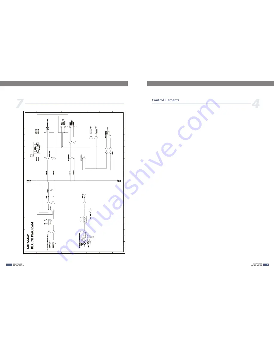
Block Diagram

10

Summary of Contents for MX.3

Page 1: ...L 12KHz 80Hz CLIP LINE USB TO MAIN CD TAPE IN L R IN OUT PEAK LEVEL LEVEL R L IN LINE 2 3 CD TAPE TO MONITOR CH1 CH2 3 MAIN MIX 10 MONITOR 0 L USB PLAY LINE IN HIGH LOW 15 15 R GAIN 0 L 15 15 R 12KHz 80Hz L R PORTABLE USB MIXER 50 PWR MAIN OUT ...

Page 2: ...MX SERIES MX SERIES ...

Page 3: ...ERIES 1 INTRODUCTION 4 2 FEATURES 4 3 INSTRUCTION 4 4 CONTROL ELEMENTS 5 5 CONNECTING DIAGRAMS 7 6 WIRING CONNECTION 8 7 BLOCK DIAGRAM 9 8 TECHNICAL SPECIFICATIONS 10 9 GUARANTEE 12 10 NOTES 13 MX SERIES 10 ...

Page 4: ... 1 Gain control in mono channel Peak LED in mono channel master 2RCA Track inputs 2RCA Track outputs 2RCA Track inputs assign to Main Mix Monitor outputs Main Mix Monitor outputs use 3 5mm stereo jack Built in stereo USB Audio interface Either USB bus powered or external adaptor 5VDC 500mA MX SERIES Make sure MX 3 mixer is used in the area of ventilation Do not install or use this product near any...

Page 5: ... Output 1K Ohms USB Interface USB 2 0 full speed compliant USB SECTION ADC DAC 16 Bit Delta Sigma 44 1kHz Sampling Rates Operating System Windows 2000 XP or higher Mac OS 9 0 4 or higher 10 X or higher Mic Pin2 Pin3 And Pin1 XLR 3 31 type balanced 1 GND 2 HOT 3 COLD 20V USB Connection DC5V 500mA Phantom power Power supply Adaptor DC5V 500mA Power Consumption 2 5W Physical Weight 0 48Kg 1 1 lbs Dim...

Page 6: ...ed to boost male or effectof drum bass 8 Type Frequency Response Distortion THD N MIC EIN Equivalent Input Noise CMRR 3 Channel USB MIXER Mic Input to any Output Gain 0 dB Rated output level 10 Hz to 40 kHz 0 1dB 10 Hz to 100 kHz 0 3dB Mic Input to MAIN Output Gain 0 dB Rated output level 20 Hz 20 kHz bandwidth 0 01 A weighted Input Channel INPUT MIC Rs 150 Gain Max 20 Hz 20 kHz bandwidth 118dBu A...

Page 7: ...mes from USB PLAY computer when the control is disengaged the signal will be from RCA jacks of channel 2 3 17 CD TAPE TO MAIN This is the assignment control of stereo line le vel When this control is engaged the signal of CD TAPE will be assigned to MAIN MIX OUT When the control is disengaged the assignment will bedisconnected 18 CD TAPE TO MONITOR This is the assignment control of stereo line lev...

Page 8: ...onnector For these applications the unit provides 1 4 TRS and XLR connectors to easily interface with most professional audio devices Follow the configuration examples below for your particular connection In line Connection Tip Ring Sleeve Tip Ring Sleeve Tip Ring Sleeve 1 2 3 1 2 3 1 2 3 TIP RING SLEEVE SLEEVE RING TIP TIP RING SLEEVE 3 Tip Ring Sleeve Tip Ring Sleeve Tip Sleeve Tip Sleeve Tip Sl...

Reviews: