MonnitLink
™
Ethernet Gateway
Quick Start Guide for Use With iMonnit Online Software
Ethernet Gateway Quick Start Overview
1. Create and setup your iMonnit™ account.
2. Connect and power on the gateway.
Important:
When setting up your sensing network, please
make sure your sensors are at least 3-5 feet away from
the gateway, and the sensors are at least 1 foot apart from
each other.
Create and Setup Your iMonnit Account
•
Visit
http://www.imonnit.com
to create an iMonnit online
sensor monitoring account.
•
Follow the on-screen instructions to enter your account
and contact information.
• You will be prompted to create your first sensor network.
Simply enter a name for your network.
•
Next you will be prompted to add a wireless gateway
and wireless sensors to your network.
•
Enter the information from your MonnitLink™
gateway then click the “Assign Gateway” button.
• Enter the information from your first wireless
sensor then click the “Assign Sensor” button.
+
_
Back of Sensor
Peel
Contains: FCC ID: ZTL-RFSC1
IC: 9794A-RFSC1
Sensor ID: ######
Sensor Code: XXXXXX
•
On the next screen, enter a name for the wireless sen-
sor and use the drop down to tell us how you are going
to be using the wireless sensor. (This allows us to sug-
gest settings for your sensor.) When finished, click the
“Continue” button.
•
Repeat these steps to add any additional wireless
sensors to your network.
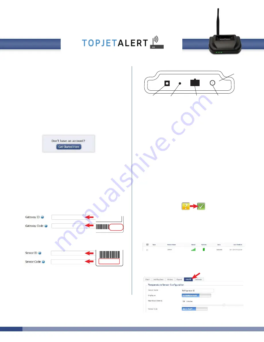
MonnitLink Ethernet Gateway Setup
Antenna Connector
Ethernet Port
Power Plug
Control Button
Back Panel
•
Attach the included antenna to the connector.
•
Plug an Ethernet cable with internet connectivity into
the gateway.
•
Plug the power supply into a power outlet then connect
to the gateway.
•
Check that the three LED lights on the front of the gate-
way change to green. Once all three lights turn green,
your network is ready to use.
(If the lights do not turn green view the Ethernet gateway trouble-
shooting guide online at,
http://www.monnit.com/support/
)
Using Your Wireless Sensors
•
From the Overview Page of iMonnit, click “View
Gateways” and check that your gateway status has
changed to active in iMonnit Express.
•
From the Overview Page of iMonnit, click “View sen-
sors” to return to the sensors overview page.
•
Click on a sensor’s information to access detailed infor-
mation for that sensor.
•
Click the “Edit” tab from a sensor’s detail view, to
change sensor settings.
Contains FCC ID: ZTL-RFSC1
and IC: 9794A-RFSC1
This device complies with Part 15 of the
FCC Rules. Operation is subject to the
following two conditions:
(1) this device may not cause harmful
interference and
(2) this device must accept any interference
received, including interference that may
cause undesired operation.
ID: ######
Code: XXXXXX
Temp Alert account.
Follow
Follow the on-screen instructions to enter your account
and contact information.
Note: If you ordered the "Advanced Plan" please contact
after you entered your contact information to activate.
you can click "view
you can click "view sen-
Visit: www.alerts.topjetsales.com
Visit: www.alerts.topjetsales.com
If you ordered the "Advanced Plan" please contact us after you
setup your contact information so that we can activate account.
alerts.topjetsales.com
Summary of Contents for Ethernet Gateway
Page 4: ......


