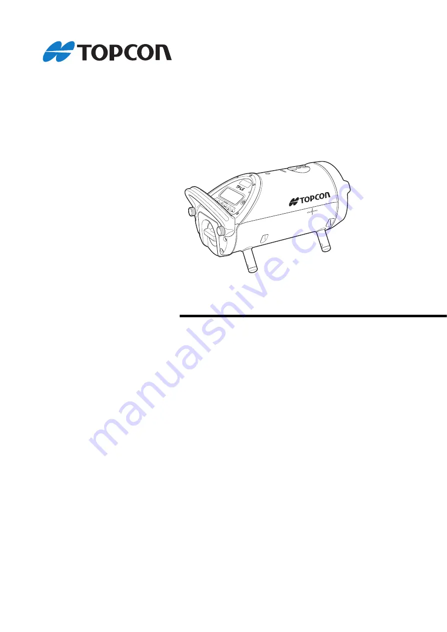
INSTRUCTION MANUALPIPE LASER
TP-L6 series
TP-L6WGVTP-L6WGTP-L6WBG
TP-L6WAVTP-L6WATP-L6WB
32956 90096
1036869-01-A
Page 1: ...INSTRUCTION MANUAL PIPE LASER TP L6 series TP L6WGV TP L6WG TP L6WBG TP L6WAV TP L6WA TP L6WB 32956 90096 1036869 01 A...
Page 2: ...the chapter title to refer to for additional information Indicates supplementary explanation Menu mode etc Indicates operation keys and selection items on the screen Notes regarding manual style Exce...
Page 3: ...of Upper Lower laser and Centerline LED 26 Setting Upper Lower laser and Centerline LED automatic power off 27 Changing the laser mode ON Blinking Energy saving 28 6 5 Setting Display Method 29 6 6 Se...
Page 4: ...ed in or near the symbol Warning Do not use the unit in areas exposed to high amounts of dust or ash in areas where there is inadequate ventilation or near combustible materials An explosion could occ...
Page 5: ...could occur resulting in fire or burns Do not use the battery or battery charger if its terminals are wet Resultant poor contact or shorting could lead to fire or burns Do not connect or disconnect po...
Page 6: ...with a cardiac pacemaker Otherwise the pacemaker may be adversely affected by the electromagnetic waves produced and cease to operate as normal Do not use onboard aircraft The aircraft instrumentation...
Page 7: ...rument is wet thoroughly wipe off with soft cloth and leave it dry before storing in the carrying case Battery The battery is not charged when the instrument is shipped Make sure to charge it fully be...
Page 8: ...ce when using Bluetooth technology Bluetooth communication with the TP L6W uses the 2 4 GHz frequency band This is the same band used by the devices described below As a result using the TP L6W within...
Page 9: ...r scattered by rain fog and moisture from the human body with the limit of usable range becoming lower as a result Similarly usable range may also shorten when performing communication in wooded areas...
Page 10: ...telecommunications regulations of the country where the instrument is being used Even exporting the wireless communication module may require conformity with the regulations Contact your local dealer...
Page 11: ...wer on make sure that persons are not located in the path of the laser beam Secure the instrument in a fixed position before it is used If it is necessary to hold the instrument by hand make sure that...
Page 12: ...e level Never point the laser beam at mirrors windows or surfaces that are highly reflective The reflected laser beam could cause serious injury Only those who have received training as per the follow...
Page 13: ...ting window TP L6WGV WAV only Laser beam window Laser beam emitted from here Grade axis mark Laser grade starting point Remote control receiving window Centerline LED TP L6WG WBG WA WB only Starting p...
Page 14: ...controller and so prevents the set values from being changed by wrong operation Press this key again to release the prohibition Key Operation When the instrument is locked p 13 Menu mode key Press to...
Page 15: ...or Upper Lower laser and Centerline LED Setting ON OFF of Upper Lower laser and Centerline LED p 26 AUTO ALIGNMENT Auto alignment The laser beam is aligned to the center of the target automatically Au...
Page 16: ...CURITY MENU mode screen Basic screen MENU 5 5 1 BLUETOOTH 1 The menu number is changed according to models 2 TP L6WGV WG WAV WA only 2 Operable functions Setting ON OFF of Centerline LED LD Changing t...
Page 17: ...ing Laser p 26 Power remaining for operation Operating time is limited Recharging or an alternate battery will be required soon Bluetooth indication The Bluetooth power supply is ON Bluetooth is alrea...
Page 18: ...adjusting process The display will appear during the adjustment of the laser after the startup of the instrument Operations can be performed just after WAIT disappears If the battery is removed while...
Page 19: ...hen the laser adjustment and reconfirmation of the grade value are necessary While RETRY LASER SETTING WAIT is displayed the key operations are impossible PRESS SET KEY will appear on the display afte...
Page 20: ...ithin the following ranges For long term storage the battery should be charged at least once every six months Batteries generate power using a chemical reaction and as a result have a limited lifetime...
Page 21: ...on Green lamp flashing On charge Green lamp lit Fully charged Yellow lamp flashing Battery temperature is out of charging temperature range Charge the battery again within the charging temperature ran...
Page 22: ...ttach the battery holder to the TP L6W 5 Attach the battery holder to the TP L6W and turn the battery holder knob to the LOCK side to fix the battery holder Before removing the battery turn OFF the TP...
Page 23: ...depending on the instrument s installed condition Warning indications p 15 For the details of Self centering Feet to be used Self centering Feet p 42 Direct entry of grade value Example Setting grade...
Page 24: ...me the display and the laser will return to 00 000 0 5 Press Right key to shift to digit B Disit B is highlighted 6 Press Down or Up key to change value to 2 7 Repeat previous steps to change values o...
Page 25: ...ght left keys of the remote controller RC 500 and move the laser emission position horizontally For the details of RC 500 refer to the following chapter 8 2 Remote Controller RC 500 p 43 6 3 Setting L...
Page 26: ...strument is locked When operating through RC 500 1 Make sure that the basic screen is indicated on the TP L6W 2 Press Laser right left keys of the remote controller RC 500 at the same time The laser w...
Page 27: ...ly align the beam to it This function is helpful for second day set ups Preparation Set the alignment target as follows Procedure Key operation Display 1 Press Menu mode key 2 Press Down key AUTO ALIG...
Page 28: ...ithin the shade or use a blower commercially available for working When using the RC 500 remote controller at close range during auto alignment mode the laser may be subject to stop outside the target...
Page 29: ...according to models When operating through RC 500 1 Make sure that the basic screen is indicated on the TP L6W 2 Press Upper Lower laser Centerline LED key Upper Lower laser or Centerline LED is ON Ea...
Page 30: ...ory setting 30 Set NO and this function is invalidated 1 Press Menu mode key and the instrument returns to the Basic screen status 2 Press Menu mode key and the instrument returns to the Procedure 1 s...
Page 31: ...re 1 status 3 The menu number is changed according to models Procedure Key operation Display 1 Press Menu mode key 1 2 Press Set Lock key 2 3 Press Down key 2 4 Press Left key or Right key to select a...
Page 32: ...g digital level vial indication when power is ON Press the power key when the power is OFF and the digital level vial indication is enlarged Press the power key again and the instrument starts Factory...
Page 33: ...enlarged indication status is released when the instrument is stabilized or when any other key is pressed Factory setting ON 4 Press Right key to highlight OFF 2 5 Press Set Lock key Setting is set t...
Page 34: ...rade value unit to or Factory setting 6 Press Set Lock key Setting is completed Procedure Key operation Display 1 Press Menu mode key 1 2 Press Down key twice 1 3 Press Set Lock key 2 4 Press Down key...
Page 35: ...control and support If TP L6W is not displayed during the pairing search in Laser Manager please complete pairing on the OS After that please do pairing again by Laser Manager When pairing with some...
Page 36: ...pply is ON Procedure Key operation Display 1 Press Menu mode key 1 2 Press Down key four times 1 3 Press Set Lock key 2 4 Press Down key 2 5 Press Set Lock key 3 Press Set Lock key again Pairing is st...
Page 37: ...For the searching method refer to the instruction manual of the software used in the smartphone For the searching method follow the instructions of the software used in the smartphone Procedure Key o...
Page 38: ...er is changed according to models 3 Press Set Lock key 2 4 Press Down key twice 2 The Bluetooth address is displayed Example 0123456789AB Press Set Lock key again and the basic screen appears again In...
Page 39: ...tering the code Procedure Key operation Display 1 Press Menu mode key 2 Press Down key three times 3 Press Set Lock key 4 Press Set Lock key 1 5 Select a numeric character by pressing the Up Down Righ...
Page 40: ...nged according to models Example Set security mode to ON Factory setting OFF 1 9 Press Set Lock key 7 1 Setting ON OFF of Security Mode Procedure Key operation Display 1 Press Power key When security...
Page 41: ...Right Left keys Example 5 7 Press Set Lock key 8 Repeat steps 6 and 7 to set remaining three code numbers Example 5246 9 Select ENT by pressing the Up Down Right Left keys MENU 1 5 1 BEAM SETTING Thre...
Page 42: ...f 32 characters can be input 2 lines of 16 characters each 10 Press Set Lock key 7 3 Changing Company Name Procedure Key operation Display 1 Press Menu mode key 2 Press Down key three times 3 Press Se...
Page 43: ...a character in the character string by pressing Right or Left keys Example LASER 1 8 Press Set Lock key 9 Repeat procedures 6 and 8 until complete 2 Using _ erase the remaining characters CON 10 Selec...
Page 44: ...es to left or right by pressing the Set Lock key 3 Select a character string by pressing the Down or Up keys 4 Select a character in the character string by pressing the Left or Right keys 5 Press Set...
Page 45: ...he target center 8 1 Self centering Feet 150mm 6 200mm 8 250mm 10 300mm 12 When the TP L6W is unstable under the condition that the four self centering feet are used for installing it can be installed...
Page 46: ...used exclusively for TP L6W You cannot operate any other instrument except TP L6W through RC 500 You cannot operate TP L6W through RC 200 To turn the laser beam ON again after the laser is turned off...
Page 47: ...w ones at the same time Insert the batteries in the battery box according to the appointed direction Do not mix used and new batteries and do not mix different types of batteries together Laser line w...
Page 48: ...D ACCESSORIES Select the size of target assembly appropriate for the pipe diameter 8 3 Target Target S Fixing screw Level vial Target holder Laser receiving side Detection strips TP L6WGV WG WAV WA on...
Page 49: ...using the laser beam and the transit or level If the distance between the readings at each point x1 and x2 are the same the unit does not need adjustment If x1 and x2 are not the same the unit require...
Page 50: ...d readjust the instrument 5 Press Set Lock key after completing the adjustment WAIT is displayed 6 When 00000 appears on the display press the Set Lock key again Repeat checking procedure above to con...
Page 51: ...laser is aligned to the center of the target 4 Rotate the instrument 180 without changing lower laser line position If the upper laser emitting position does not change more than 4mm the unit is with...
Page 52: ...around the laser may cause this error Eliminate vibration E 04 The angle is not measured properly Contact your local dealer E 05 The laser s positioning is not adjusted properly Switch OFF the power t...
Page 53: ...1 Press the Set Lock key on the instrument to release the lock function 2 Grade entry must be in the range of 15 to 40 3 Reposition the instrument until the level warning indicator disappears 4 Rechar...
Page 54: ...justed correctly 3 The laser beam is refracted due to temperature differences within the pipe 1 Confirm the input value or and reset 2 Adjust the laser and or target so the bubble is centered 3 When t...
Page 55: ...Single point foot model 2 Trivet stand model 4 Trivet handle model 2 Tripod adapter model 3 Scope model 2 Over the top target Optional accessories which are sold separately may be subject to change or...
Page 56: ...prox 4 Rotating direction Approx 2 Vertical accuracy Rolling direction Upper 1 5 Lower 3 5 Bluetooth wireless communication 1 TP L6WGV WG WBG WAV WA WB Transmission method FHSS Modulation GFSK Frequen...
Page 57: ...e temperature range 30 to 60 C 22 to 140 F Water resistance IPX8 IEC 60529 2001 when the battery holder is attached Size 125mm X 250mm without handle 125mm X 280mm with rear handle Weight about 3 0kg...
Page 58: ...on the user is encouraged to try to correct the interference by one or more of the following measures Reorient or relocate the receiving antenna Increase the separation between the equipment and rece...
Page 59: ...S 003 Cet appareil numerique de la Class B est conforme a la norme NMB 003 du Canada This equipment complies with IC radiation exposure limits set forth for an uncontrolled environment and meets the R...
Page 60: ...states only Following information is only for EU member states The use of the symbol indicates that this product may not be treated as household waste By ensuring this product is disposed of correctl...
Page 61: ...https www topcon co jp GLOBAL GATEWAY https global topcon com Please see the following website for contact addresses 2020 TOPCON CORPORATION ALL RIGHTS RESERVED...