background image


30 


3.2  REFERENCE DATA SETTING 

Set the reference data for the difference and the percenteage mode.


The reference data is common between for the difference and the percentage.


When  the  reference  data  is  not  entered,  the  reference  data  entry  screen  appears  after 

pussing [

] switch or [%] switch.


When there is no reference data, [0000] appears and the reference data entry screen 

is available.


3.2.1  PROCEDURE FOR REFERENCE DATA ENTRY


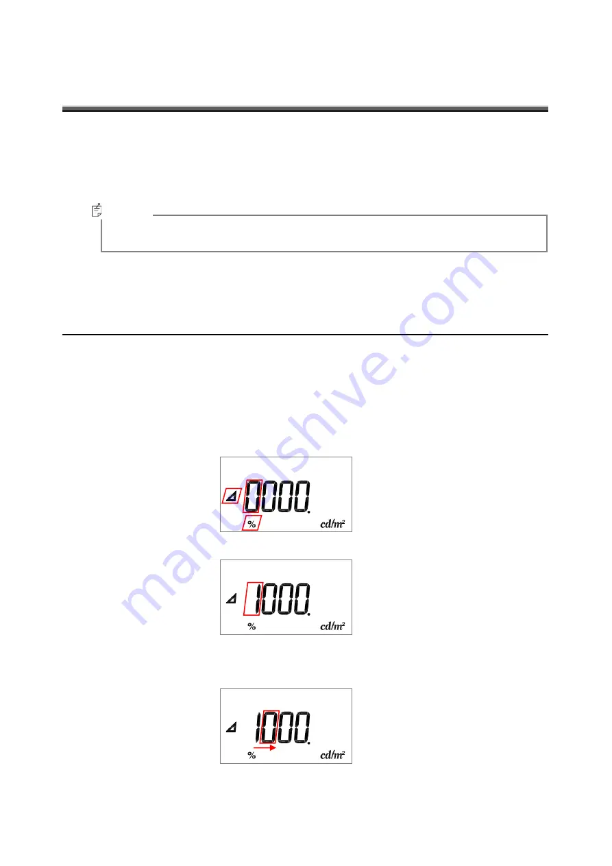
- Enter specified value as reference data 

ex

  entyr of 150.0


1


Press [

] swith or [%] switch.


2


Reference data entry is available and the digit at the left end is blinking.


When you press [

] swith at step, [

] mark appears on the display. When you pres 

[%] switch, [%] mark appears.


3


Press [0

9] switch to change the figure.


4


Press [SHIFT] switch and the second left digit is blinking.


Change the value by pressing [0

9] switch in the same way.


  Memo


Summary of Contents for BM-9A

Page 1: ...INSTRUCTION MANUAL LUMINANCE METER Rev 7...

Page 2: ......

Page 3: ...ject to strong shock caused by falling etc to this instrument and do not use or store the instrument in or on a place with continuous vibration This instrument contains precision components which may...

Page 4: ...2 This instrument is made of recyclable materials When you dispose of this instrument please consign this instrument to recycle dealer...

Page 5: ...dicates that incorrect handling with disregard for this display may cause accidents resulting in injury 1 or damage to property 2 1 This refers to injury such as burns electric shock or the like that...

Page 6: ...C adapter malfunctions may result in fire or electric shock Do not disassemble the AC adapter Doing so might cause fire or electric shock Remove dust or moisture from the AC adapter plug Failure to do...

Page 7: ...s caused by use or out of commission of this instrument TOPCON TECHNOHOUSE accepts no responsibility for any damages caused by use other than that instructed in the instruction manual TOPCON TECHNOHOU...

Page 8: ...22 2 5 COLOR CORRECTION FACTOR C C F 23 2 6 DIFFERENCE MODE 24 2 7 PERCENTEAGE MODE MODE 25 2 8 ZERO ADJUSTMENT CAL 26 2 9 HOW TO USE THE ANALOG OUTPUT CONNECTOR 27 3 SETTING PROCEDURES 28 3 1 CORRECT...

Page 9: ...7 GRAPH 47 EXPLANATION OF TERMS 49...

Page 10: ...on a keyboard and the display of the instrument Indicates a text referred to in this manual Indicates other instruction manual to be referred to Request Explains matters to be acknowledged or to be co...

Page 11: ...hree type of detector unit are available Option Measuring Angle 2 BM 9A20D Measuring Angle 1 BM 9A10D Measuring Angle 0 2 BM 9A02D Accessories USB Driver instruction manual 1 Quick manual 1 Leather ca...

Page 12: ...nd strap USB connector Object lens Control unit Keyboard DC power input connector Screw for mounting tripod 1 4 screw Depth 5mm Analog output connector Name Plate Serial Number Eyepiece Three types of...

Page 13: ...ponse switch Range Response speed 90 FAST 1 About 22 ms 2 About 2 ms 3 About 1 ms 4 About 1 ms 5 About 1 ms SLOW 1 5 About 1 s or less Hold switch By pushing this hold switch during measurement Measur...

Page 14: ...sured value and the reference data Or use this switch to set the reference data CALL During Percentage or Difference mode Press this switch for 3 seconds to display reference data CAL Calibration Star...

Page 15: ...on factor setting Blingking when correction factor is active Appears during the difference mode or the reference data entry Either or appears to indicate the difference between the measured value and...

Page 16: ...OW TO MOUNT THE DETECTOR UNIT Push in the detector along with the connector guide in the arrow direction Be sure to turn off the power switch before connecting disconnecting the detector unit Insert D...

Page 17: ...chase those at your dealer 1 Turn the power switch off and uncover the battery compartment 2 Insert a battery according to a polar indication shown on the battery compartment 3 Mount the battery compa...

Page 18: ...r the AC adapter Otherwise it may cause fire Do not remove or insert the plug with wet hands Otherwise it may cause electric shock Procedure for connection of the AC adapter to this instrument is as f...

Page 19: ...out while the instrument power is on Connector Pin Assignment Communication parameters This instrument conducts USB communications through a virtual COM port When you prepare your own communication p...

Page 20: ...r zero adjustment Response switch 2 2 Setting Response Switch The time required to complete zero adjustment differs depending on the setting of the response switch FAST about 15 seconds SLOW about 50...

Page 21: ...into the eyepiece and turn the diopter adjustment ring of the eyepiece so that the reticle marks are clearly seen in the view finder 3 Collimate the measurement object and turn the focus ring of the o...

Page 22: ...turning on the power and zero adjustment 2 3 1 AUTO RANGE MEASUREMENT 1 Remove the cap and start measurement 2 The readout appears on the panel When the readout is stabilized read the value Turn on t...

Page 23: ...itches to manual range 3 Pushing the MANU RANGE switch to advance to the range as follows 1 2 3 4 5 4 A measured value appears in the display read the value when it becomes stable To fix the readout P...

Page 24: ...nit cd m2 Measuring Field Range 1 2 3 4 5 2 BM 9A 20D Measurment Range 0 01 28 00 0 1 280 0 1 2 800 10 28 000 100 280 000 Resolution 0 01 0 1 1 10 100 1 BM 9A 10D Measurment Range 0 1 280 0 1 2 800 10...

Page 25: ...s multiplied by measured value and correction factor How to release correction factor C C F 1 Press C C F switch during Luminance measurement 2 When correction factoir is not active the 0 mark disappe...

Page 26: ...asurement 2 In the difference mode the mark appears on the left side of the display The value on the display is a difference between the measured value and the reference data 3 Press switch again to r...

Page 27: ...luminance measurement 2 The mark appears on the down side of display The readout is percentage of the measured value to the reference data 3 Press switch again to return to luminance measurement mode...

Page 28: ...tment starts automatically after turning on power Zero adjustment can be conducted regardless of whether the response switch is set to FAST or SLOW The Duration of zero adjustment vary from response s...

Page 29: ...nce of the instrument is not more than 100 ohm The analog output voltage is calibrated to 2 800V at peak The resolution varies depending on the range The maximum output voltage is up to 3 V in manual...

Page 30: ...r 1 Press C C F switch for several seconds 2 The digit at the left end is brinking and the 0 mark appears on the top of display and Correction factor entry is available 3 Change the value by pressing...

Page 31: ...is active readout is the value multiplied measured value and correction factor Color correction factor applied 2 5 COLOR CORRECTION FACTOR Valid range of correction factor is from 0 001 to 1 000 When...

Page 32: ...0000 appears and the reference data entry screen is available 3 2 1 PROCEDURE FOR REFERENCE DATA ENTRY Enter specified value as reference data ex entyr of 150 0 1 Press swith or switch 2 Reference dat...

Page 33: ...ction factor Press SHIFT switch several times to move the digit you want to chage 0 can be entered only at the fifth and sixth digit from the left Valid range of the reference data is from 0 001 to 99...

Page 34: ...eference data appears for 3 seconds 5 Release Hold switch Press switch or switch to go to the difference or the percentage mode When correction factor is active readout is multiplied by correction fac...

Page 35: ...ENCE DATA 1 Press switch or switch to enter the difference or the percentage mode 2 Press CALL switch 3 The active reference data is displayed for about 3 seconds and then returning to the difference...

Page 36: ...ites correction factor C C F into EEPROM of the BM 9A Enters correction factor with decimal notation or or exponent notation E Range to enter 0 001 1000 RCCF Reads correction factor C C F E ASCF_ Acti...

Page 37: ...Rn Cr Lf OK Cr Lf Measured value Data Cr Lf END or NG Cr Lf 4 1 2 CAL COMMAND When the BM 9A receive this command the BM 9A starts zero adjustment When BM 9A receives this command during integral lumi...

Page 38: ...version production serial number Data Cr Lf END Cr Lf 4 1 4 SCCF COMMAND When the BM 9A receives this command the BM 9A writes C C F into EEPROM of the BM 9A Valid values range from 0 001 to 1000 PC C...

Page 39: ...Lf 4 1 7 ARCF COMMAND When the BM 9A receive this command the BM 9A return a status about whether color correction factor C C F is active or inactive PC Command BM 9A ARCF Cr Lf OK Cr Lf Data Cr Lf E...

Page 40: ...the same as that in display unit R measns measuremtne range UC means Unit Cd m2 WHO BM 9A02D or BM9A10D or BM 9A20D The name of currenty attached detector VER Software version SRL Displays production...

Page 41: ...gistered trademark of Microsoft Corp in the US The following describes the procedure for installing the USB drive into PCs For Windows XP 1 Insert the CD ROM supplied with the BM 9A into CD ROM drive...

Page 42: ...40 To uninstall click Uninstall button for step 4 above The following 2 types of drivers are installed Serial converter Serial port Memo Memo...

Page 43: ...sing manual range change the measurement range to upper range When C C F is On set Off of C C F E6 The instruments fail to write or read data Contact your dealer or Topcon Technohouse E7 E8 Values you...

Page 44: ...ur dealer or Topcon Technohouse 4 5 Measured values exceed measurable range Check if the measurement range is appropriate When using manual range change the measurement range to upper range When C C F...

Page 45: ...distance covers from the objective lens hardware tip to the target Spectral sensitivity characteristics Within 6 deviation from the relative luminous efficiency Luminance accuracy 2 or rdg 2digit Stan...

Page 46: ...requency energy and if not installed and used in accordance with the instruction manual may cause harmful interference to radio communications Operation of this equipment in a residential area is like...

Page 47: ...013 G 54 0 993 B 46 0 996 T 44 1 003 Lamps Fluorescent lamp F6 0 989 Fluorescent lamp F8 0 989 Fluorescent lamp F10 0 992 High pressure sodium lamp NAV TS70W SUPER 0 993 Mercury fluorescent lamp HF40...

Page 48: ...ower switch Battery Analog output Visual COM port KEYBOARD UNIT KeyBoard LC display LIQUID CRYSTAL DISPLAY Control unit MICRO PROCESSOR A D CONVERTER INTEGRAL CALCULUS CIRCUIT Silicon photo diode Ligh...

Page 49: ...47 OUTLINE DIMENSION BM 9A...

Page 50: ...efficacy BM 9A The above data are obtained by a sample of this instrument There are some differences in the characteristics between the products Deviation from spectral luminous efficacy IM 600 Spect...

Page 51: ...onsivity of the BM 9A closely matches the spectral luminous efficiency The difference between spectral luminous efficacy and Relative spectral response of the BM 9A is evaluated according to JIS C1609...

Page 52: ...le 1 Maintenance and repair parts mean the parts that are necessary to maintain the function of the product 2 Topcon Technohouse make our most effort to keep maintenance and repair parts in stock for...

Page 53: ...bration Tel 81 3 3558 2710 Fax 81 3 3558 3011 LUMINANCE METER BM 9A INSTRUCTION MANUAL Date of issue 7th edition January 2017 Issued by TOPCON TECHNOHOUSE CORPORATION 75 1 Hasunuma cho Itabashi ku Tok...

Reviews: