background image

MAINTENANCE AND TROUBLESHOOTING 

30 


If there is any problem and has no the authorized professional maintenance personal, please 

contact local agent or the branch company! 


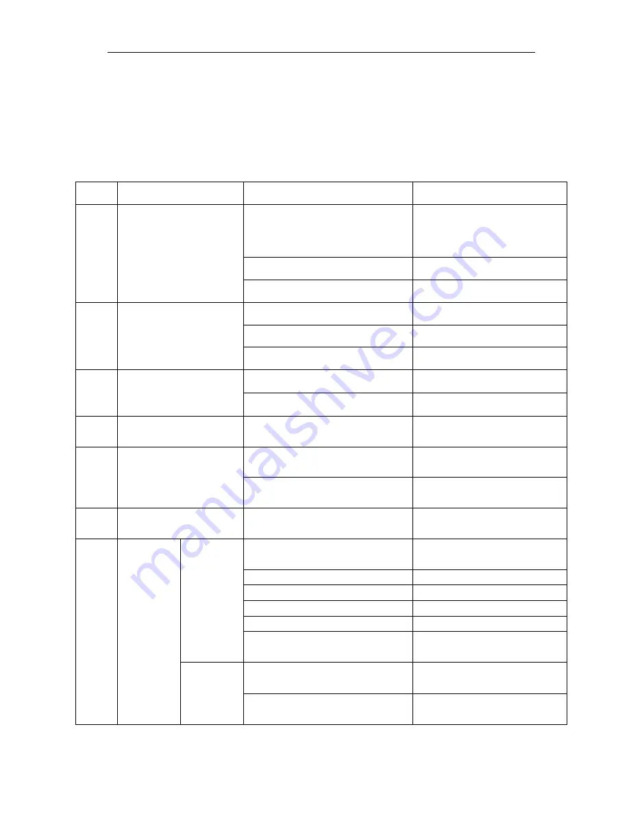
If there are some simple troubles of TIG200E AC/DC -series welding machine, you can consult the 

following overhauling chart: 


S/N 

Troubles 

Reasons 

Solution 

Turn on the power source, and 

fan works, but the power pilot 

lamp is not on.   

The power light damaged or connection is 

not good 

Check and repair Pr7 

The transformer of power is broken 

Repair or change the transformer 

Control PCB failures 

Repair or change the control Pr4 

Turn on the power source, and 

the  power lamp is on, but fan 

doesn’t work   

There is something in the fan 

Clear out 

The start capacitor of fan damaged 

Change capacitor 

The fan motor damaged 

Change fan 

Turn  on the power source, the 

power lamp is not on, and  fan 

doesn’t work 

No power supply input 

Check whether there is power supply 

The fuse inside the machine damaged 

Change it (3A) 

The number on the display is not 

intact.   

The LED in the display is broken 

Change the LED 

The max and min value 

displayed doesn’t accord with 

the set value. 

The max value is not accordant (refer to


§3.1) 

Adjust potentiometer Imin on the power 

board. 

The min value is not accordant (refer to


§3.1) 

Adjust potentiometer Imaxin the current 

meter. 

No no-load voltage output 

(MMA) 

The machine is damaged   

Check the main circuit and the Pr4. 

Arc can not be 

ignited (TIG) 

There is spark 

on the HF 

igniting board. 

The welding cable is not connected with the 

two output of the welder. 

Connect the welding cable to the 

welder’s output. 

The welding cable damaged. 

Repair or change it. 

The earth cable connected unstably. 

Check the earth cable. 

The welding cable is too long. 

Use an appropriate welding cable. 

There is oil or dust on the workpiece. 

Check and remove it. 

The distance between tungsten electrode and 

workpiece is too long. 

Reduce the distance (about 3mm). 

There is not 

spark on the 

HF igniting 

board. 

The HF igniting board does not work. 

Repair or change Pr8 

The distance between the discharger is too 

short. 

Adjust this distance (about 0.7mm). 

Summary of Contents for TIG 202E AC/DC

Page 1: ...anual Completely before attempting to use this equipment Save this manual and keep it handy for quick reference Pay particular attention to the safety instructions we have provided for your protection...

Page 2: ...OLARITY CONNECTION MMA 12 3 6 ASSEMBLING THE EQUIPMENT TIG 13 4 OPERATION 14 4 1 LAYOUT FOR THE PANEL 14 4 2 CONTROL PANEL 15 4 3 1 PEDAL SWITCH CONTROL 19 4 3 2 GUN SWITCH CONTROL CURRENT 19 4 4 ARGO...

Page 3: ...equipment according to 5 because of the DC voltage existing in the electrolytic capacitors ELECTRIC SHOCK CAN KILL Never touch electrical parts Wear dry hole free gloves and clothes to insulate yourse...

Page 4: ...elding with electrodes which require special ventilation such as stainless or hard facing or on lead or cadmium plated steel and other metals or coatings which produce highly toxic fumes keep exposure...

Page 5: ...re refueling to prevent spilled fuel from vaporizing on contact with hot engine parts and igniting Do not spill fuel when filling tank If fuel is spilled wipe it up and do not start engine until fumes...

Page 6: ...hazards or overheat lifting chains or cables until they fail Rotating parts may be dangerous Use only compressed gas cylinders containing the correct shielding gas for the process used and properly o...

Page 7: ...minimize exposure to EMF as few as possible In order to minimize EMF we should use the following procedures Route the electrode and work cables together Secure them with tape when possible All cables...

Page 8: ...ss ratio of igniting arc TIG200E AC DC Characteristics MCU control system responds immediately to any changes High frequency and high voltage for arc igniting to ensure the success ratio of igniting a...

Page 9: ...s quickly which can reduce the possibility to produce hot crack of the materials with thermal sensitivity 2 The workpiece gets little heat Arc energy is focused Be suitable for thin sheet and super th...

Page 10: ...out 312V then is converted to medium frequency AC about 40KHz by inverter device IGBT module after reducing voltage by medium transformer the main transformer and rectifying by medium frequency rectif...

Page 11: ...wn as the following figure The relation between the conventional rated loading voltage U2 and the conventional welding current I2 is as follows When I2 600A U2 10 0 04I2 V When I2 600A U2 34 V 67 34 1...

Page 12: ...8 9 DC MMA Duty cycle 40 10 minutes AC TIG MMA DC TIG AC TIG MMA DC TIG 35 200A 40 170A 35 200A 40 170A 60 155A 60 140A 60 155A 60 140A 100 120A 100 110A 100 120A 100 110A No load voltage V 52 52 Adju...

Page 13: ...front panel At this time the machine should be relaxed for 15 minutes to cool the fan When operating the machine again the welding output current or the duty cycle should be reduced 3 3 Movement and p...

Page 14: ...range it will shorten the welder life span The below measures can be used Change the power supply input net Such as connect the welder with the stable power supply voltage of distributor Induce the ma...

Page 15: ...ECTION in TIG welding mode The control cable of torch switch consists of 2 wires pedal control of 3 wires and the aero socket has 14 leads Consumable parts for TIG torch such as tungsten electrode tip...

Page 16: ...rol wire It has 14 leads and lead 8 lead 9 are connected to torch switch control wire 4 Shield gas connector Is connected to the gas input pipe of torch 5 Power source switch Switch to ON the welder i...

Page 17: ...INSTALLATION AND ADJUSTMENT 15 4 2 Control panel TIG 200E AC DC...

Page 18: ...INSTALLATION AND ADJUSTMENT 16 TIG 200E AC DC PULSE...

Page 19: ...rrent only with 4T Unit A Setting range 10 170 DC 10 200 AC Tup Upslope time Unit S Setting range 0 0 10 Ip Welding current Unit A 10 170 TIG DC 10 200 TIG AC Ib Base current Unit A 10 170 TIG DC 10 2...

Page 20: ...with 4T Unit A Setting range 10 170 DC 10 200 AC Tpo Gas post flow time Unit S Setting range 0 10 Balance only with TIG AC Balance adjustment is mainly used to set the adjustment of eliminating metal...

Page 21: ...max current you want The eighth and ninth of the fourteen lead aero socket is gun switch The first and second of the fourteen lead aero socket is short circuit The third fourth and fifth of the fourte...

Page 22: ...witch the output current slopes up from the start current t2 t3 The output current rises to the setting value Iw or Ib the upslope time can be adjusted t3 t4 Welding process During this period the gun...

Page 23: ...gas time 0 2s t1 t2 Arc is ignited and the output current rises to the setting welding current Iw or Ib from the min welding current t2 t3 During the whole welding process the gun switch is pressed an...

Page 24: ...rent will drop a half then if the TIG torch is pressed quickly again the welding current will get back Notices Check the condition of welding and connection units firstly otherwise there will be malfu...

Page 25: ...ding area color protect effect of Ti alloy Welding area color bright argent orange yellow blue purple caesious white powder of titanium oxid Protect effect best better good bad worst 4 5 3 TIG Paramet...

Page 26: ...sharpened of the electrode diameter mm angle of cone background current A 1 0 0 125 12 2 15 1 0 0 25 20 5 30 1 6 0 5 25 8 50 1 6 0 8 30 10 70 2 4 0 8 35 12 90 2 4 1 1 45 15 150 3 2 1 1 60 20 200 TIG...

Page 27: ...side 2 2 2 5 2 3 90 120 8 12 8 12 Butt welding Parameters of piping back sealing welding for mild steel DCEP Piping diameter mm Tungsten electrode diameter mm Gas nozzle diameter mm Welding wire diame...

Page 28: ...5 5 6 6 7 200 260 360 400 30 35 20 22 Notice the above parameters originate from Welding Dictionary P538 Volume 2 of Edition 2 4 6 Operation Environment Height above sea level is below 1000m Operation...

Page 29: ...ed Do not touch the output electrode with any part of your body Before operation no concerned people should be left Do not watch the arc in unprotected eyes Ensure good ventilation of the machine to i...

Page 30: ...r turn on power watch listen to that whether the arc welding machine has shaking whistle calling or peculiar smell If there is one of the above problems find out the reason to get rid of if you can t...

Page 31: ...ent value can be measured by the adjusted plier type ampere meter Yearly examination Measure the insulating impedance among the main circuit PCB and case if it below 1M insulation is thought to be dam...

Page 32: ...ine damaged Change it 3A 4 The number on the display is not intact The LED in the display is broken Change the LED 5 The max and min value displayed doesn t accord with the set value The max value is...

Page 33: ...T module damaged Change it 12 The welding current displayed isn t accordant with the actual value The min value displayed isn t accordant with the actual value Please refer to 3 1 Adjust potentiometer...

Page 34: ...MAINTENANCE AND TROUBLESHOOTING 32 5 3 Electrical principle drawing...

Page 35: ...MAINTENANCE AND TROUBLESHOOTING 33...

Reviews: