Top Flite Cessna 182 ARF User Manual Download Page 27

27

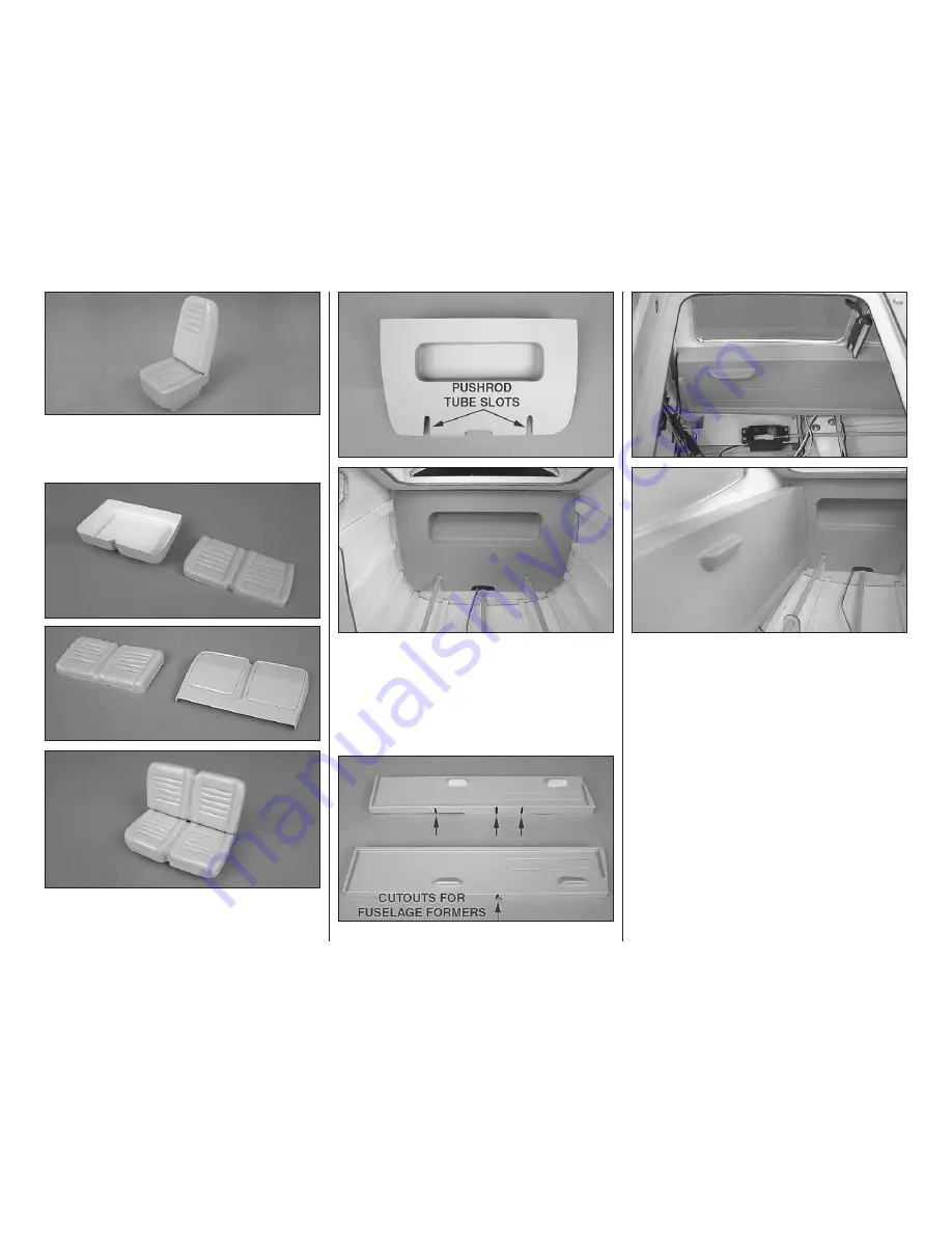
4. Fit the assembled seat back to the seat bottom. 

Make  any  final  adjustments  to  the  fit  and  glue  the 
assemblies together.

5. The back seat is assembled in the same manner 

as the front.

6. Cut out the cockpit back panel. Slots will need to be 

made for the elevator and rudder pushrod tubes, as well 
as a cutout for the tail light wire to pass under. The piece 
should sit flat against the fuselage former just behind 
the back window. Glue the cockpit back in place.

Work slowly during step 7 to cut cockpit side panels 
that fit well.

7.  Rough  cut  the  cockpit  side  panels  leaving  as 

much material as possible. Slots will need to be cut 
at the top and bottom of the pieces to fit around the 
fuselage formers. Temporarily fit the pieces in place 
and  use  a  felt-tip  pen  or  pencil  to  mark  the  center 
of each former onto the side pieces where they will 
need to be trimmed (be careful not to get pen marks 
in areas that will not be cut away since the ink would 
be difficult to remove from the painted pieces). With 
the  slots  cut  in  the  correct  positions,  carefully  start 
trimming  the  top,  outside  edges  of  the  side  panels. 
The  top  of  the  panels  should  rest  on  the  fuselage 
stringers that are located just below the side windows. 
Trim these edges so that there are no gaps between 
the  top  edges  of  the  side  panels  and  the  fuselage 
sides.  The  panels  will  need  to  be  gently  forced 
against the fuselage sides to follow the contour of the 
fuselage. When satisfied with the fit, finish sand the 
edges and glue the panels in place.

Summary of Contents for Cessna 182 ARF

Page 1: ...pared to accept the liability associated with the use of this product the buyer is advised to return this kit immediately in new and unused condition to the place of purchase To make a warranty claim...

Page 2: ...cally won t find in other scale ARF planes Although the Cessna 182 ARF already includes an impressive list of these extras right out of the box the sky is the limit for the amount of additional scale...

Page 3: ...h the Cessna182ARFthatmayrequireplanningordecision making before starting to build Order numbers are provided in parentheses Building Stand A building stand or cradle comes in very handy during the bu...

Page 4: ...Order numbers are provided in parentheses o R C foam rubber 1 4 6mm HCAQ1000 or 1 2 13mm HCAQ1050 o 3 900mm Standard silicone fuel tubing GPMQ4131 ADHESIVES BUILDING SUPPLIES In addition to common ho...

Page 5: ...p Flite Cessna 182 ARF use the order numbers in the Replacement Parts List that follows Replacement parts are available only as listed Not all parts are available separately an aileron cannot be purch...

Page 6: ...20 18 19 19 7 6 1 10 8 2 12 9 4 33 34 13 14 16 26 17 32 2 27 35 2 27 23 28 30 29 29 22 21 25 6 5 31 24 3 11 15...

Page 7: ...ol surfaces Use a covering iron with a covering sock on medium high heat to tighten the covering if necessary Apply pressure over sheeted areas to thoroughly bond the covering to the wood ASSEMBLE THE...

Page 8: ...e pockets in the flap and wing as was done in step 1 Use a paper towel dampened with denatured alcohol to clean up any epoxy Work the flap up and down to ensure it moves freely Look at the flap from t...

Page 9: ...hen the CA has dried gently pull on the aileron to confirm that it is securely glued in place o 8 Repeat steps 1 7 for the left wing panel INSTALL the AILERON SERVO LINKAGE Before completing this sect...

Page 10: ...into each hole and back it out Apply a drop of thin CA to each hole to harden the wood When the CA has dried install the servo onto the hatch cover using the hardware supplied with the servo o o 5 Us...

Page 11: ...to 10 for the left wing panel INSTALL the FLAP SERVO LINKAGE o o 1 As you did with the aileron glue the mounting blocks to the underside of the flap servo hatch cover When the epoxy has cured attach...

Page 12: ...o pull the wingtip light wires through the wing panels Use epoxy to glue the wing tips to the wing being sure that the curved tips point to the underside of the wing Align the tops and bottoms of the...

Page 13: ...atisfied with the fit of the wing panels and center section mix up approximately 1 oz 30cc of 30 minute epoxy and coat the inside of the wing joiner pockets in each wing panel and center section Coat...

Page 14: ...slot in the stab If the hinges are difficult to install use a hobby knife to slightly enlarge the slots Roughen the ends of the elevator joiner wire and clean them with alcohol Test fit the elevators...

Page 15: ...another 5 32 4mm wheel collar Hold a wheel pant against the base of each landing gear leg and center the wheels in the pants Mark the location of the wheel collars onto the axles remove the hardware a...

Page 16: ...ach the strap to the wheel pant using two 4 x 3 8 9 5mm self tapping screws o 9 Cut the nylon nose gear bearing block into two pieces as shown and flip them over Sand the top and bottoms of the pieces...

Page 17: ...rms opposite each other from a four armed servo arm for your rudder servo Enlarge the second inner holes in both remaining arms with a 5 64 2mm drill bit Install the servo arm perpendicular to the len...

Page 18: ...as the accessible area behind the hole Cut a piece from the included outer pushrod tube 7 1 4 184mm long Insert the tube through the large hole behind the steering arm on the nose wheel and through th...

Page 19: ...ation only contains information relevant to that particular power system so you can skip directly to the section that matches your choice of power systems GLOW ENGINE INSTALLATION The installation of...

Page 20: ...drilling a hole for the throttle pushrod o 5 Using four 8 32 x 1 1 4 32mm SHCS four 8 flat washers four 8 lock washers and threadlocking compound attach the engine mount on its side to the firewall Po...

Page 21: ...ular to the servo case pointing to the center of the fuselage Be sure to install the servo arm screw Thread a nylon clevis and silicone clevis retainer onto a 12 305mm pushrod Fit the pushrod through...

Page 22: ...threadlocking compound and securely tighten all screws o 4 Make a hook and loop strap for your ESC from the included hook and loop material by overlapping mating ends by approximately 1 25mm The total...

Page 23: ...ed as far forward as it will go confirm that the tab is holding the receiver tray down by gently pulling upward on the tray When satisfied drill a 1 16 1 6mm hole through the screw hole on the receive...

Page 24: ...cowl Use the spinner backplate to ensure that the cowl is centered When satisfied tape the cowl in place Mark the cowl 3 8 9 5mm forward of the aft edge of the cowl at the center of each mounting blo...

Page 25: ...Small pieces can be cut from the scrap covering to fill in the exposed plywood edges at the corners of the windows Trim off the remaining covering as necessary o 2 Use canopy scissors to trim the rea...

Page 26: ...ugged into the flap channel and one plugged into the aileron channel Glue the heat shrink tubing to the sides of the fuselage in the location shown Doing so will provide easy access to plug in the fla...

Page 27: ...m of the pieces to fit around the fuselage formers Temporarily fit the pieces in place and use a felt tip pen or pencil to mark the center of each former onto the side pieces where they will need to b...

Page 28: ...om shoulders of the side panels If the floor will not fit between the side panels remove it and carefully trim it narrower until a good fit is achieved We notched the back of the panel and folded the...

Page 29: ...e 4 x 45mm SHCS FINAL TOUCHES o 1 Locate the small pin holes in the covering on the fuselage and wing for the wing struts Align the holes in the wing struts over the pin holes in the covering and conf...

Page 30: ...scissors or a sharp hobby knife to cut the decals from the sheet 2 Be certain the model is clean and free from oily fingerprints and dust Prepare a dishpan or small bucket with a mixture of liquid di...

Page 31: ...s that hold on the servo arms o 2 With the transmitter and receiver still on check all the control surfaces to see if they are centered If necessary adjust the clevises on the pushrods to center the c...

Page 32: ...ng characteristics Moving the C G forward may improve the smoothness and stability but the model may then require more speed for takeoff and make it more difficult to slow for landing Moving the C G a...

Page 33: ...Balancer GPMQ5000 in our flight box GROUND CHECK Iftheengineisnew followtheenginemanufacturer s instructions to break in the engine After break in confirm that the engine idles reliably transitions sm...

Page 34: ...n front of which all flying takes place with the other side for spectators Only personnel involved with flying the aircraft are allowed at or in the front of the flight line Intentional flying behind...

Page 35: ...Not mounting control horns solidly Poor fit of clevis pin in horn Side play of wire pushrods caused by large bends Excessive free play in servo gears Insecure servo mounting and one of the most preva...

Page 36: ...ust use the elevator to establish a shallow climb It is preferred to have the flaps up or at half setting for takeoffs and climb outs because the plane will accelerate and climb much better Have a bal...

Reviews: