background image

STEP 3

Step-3

68

M5*12

D15.4

M8*20

D16

9

8

x4

7

41

D15.4 D16

8

x4

7

M8*50

x2

3-1

a

b

d

c

3-5

3-2

3-3

3-4

10

49

9

7

8

81

81

67 68

81

67

41

8

7

87

29

30

9

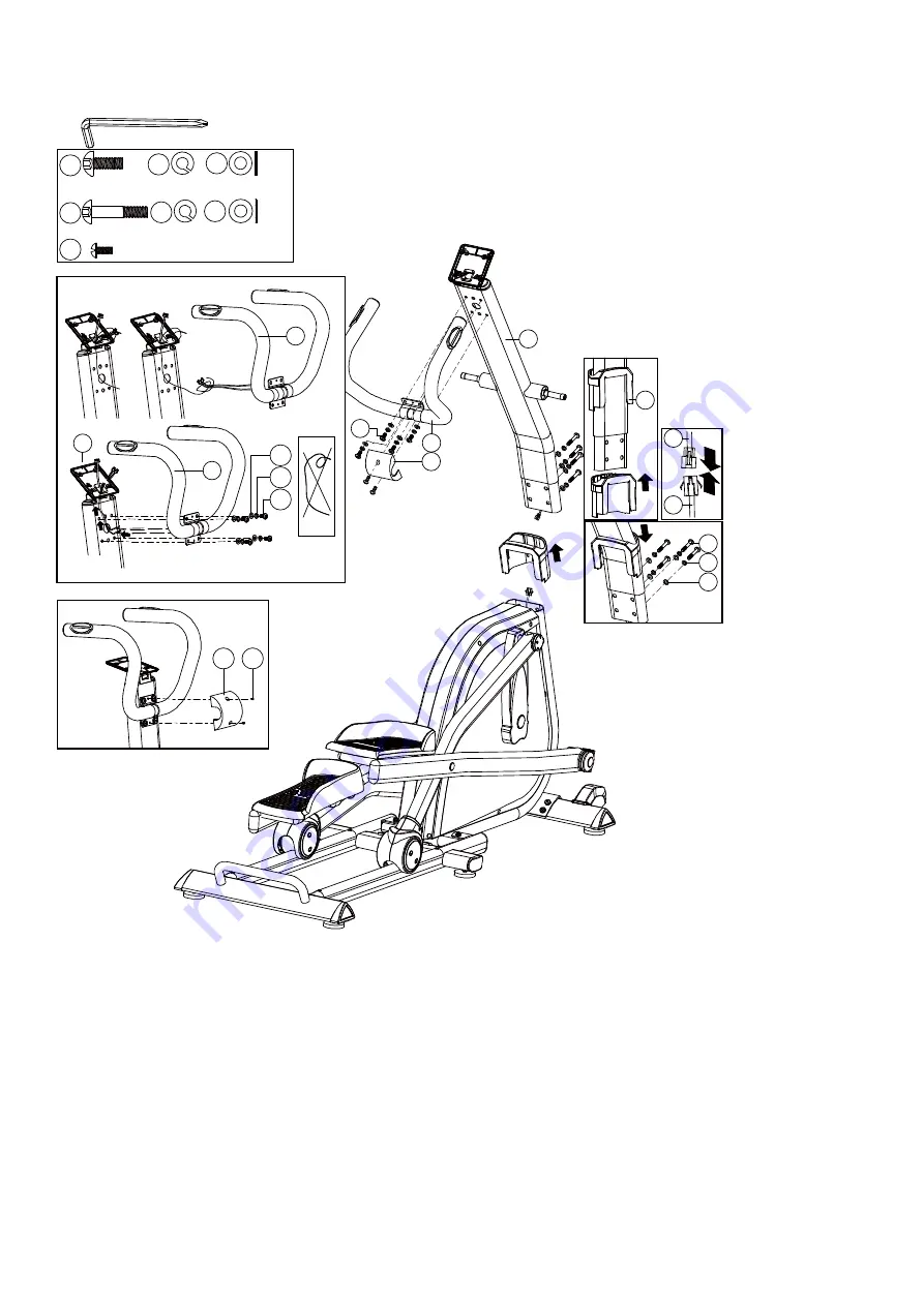
1) Suggest assembling this step by two persons.
2) First, lift up the upper protective cover  (49) as fig. 3-1. Then connect computer

cable (29 & 30) as fig.3-2.

3) Insert the handlebar post (10) on the main frame and tighten it by using the flat

washer (8), the spring washer (7) and the Allen bolt (41). Place down the upper
protective cover (49) and make it tight on the main frame as fig.3-3.

4) Assemble the handlebar welding set (81) to the handlebar post (10) by using the

flat washer (8), the spring washer (7), and the Allen bolt (9) as fig.3-4.

5) Assemble the protective cover (67) by using the bolt (68) as fig.3-5.

14

Summary of Contents for ERX3500

Page 1: ...Ed 10 18 Rev 00 INSTRUCTION iConsole App Manual www toorx it iconsole ...

Page 2: ...0L 4pcs 41 M8 1 25 20 L 4P CS 9 D15 4 D8 2 2T 8PCS 7 D16 D8 5 4pcs 8 D16 D8 5 8pcs 8 M5 12L 2PCS 68 D25 D8 5 2 T 2P CS 46 M8 1 25 20 L 2PCS 9 M8 1 25 20 L 6PCS 9 D25 D8 5 2 T 2PCS 46 D15 4 D8 2 2 T 4PCS 7 D22 D8 5 1 5 T 4P CS 6 14 D26 D19 5 2P CS D24 D10 2P CS 47 23 D50 2P CS D46 2PCS 90 68 18 D29 D20 0 9 T 2P CS D24 D10 2P CS 47 D27 D8 2 2 5T 2P CS 1 2 10 12 L R 64 49 11 L R 93L R 81 19 44 21L R ...

Page 3: ...5 62 49 37 36R 36L 64 101 87 83 55 53 52R 52L 12L 12R 27 18 81 15 65 89 47 70 94 50 56 60 16 75 25 29 30 106 86 22 45 34 43 27 43 58 42 72 73 88 92 99 102 104 97 98 80 77 78 42 9 41 105 84 82 67 68 40 8 105 20 47 91 26 28 96 68 14 51 109 111 110 23 71 54 13 46 97 118 44 85 138 9 7 8 22 17 59 46 46 46 76 7 9 84 84 46 6 48 43 13 7 ...

Page 4: ...r 1 12R Supporting tube for right movable handlebar 1 13 Spacer NL66 D21 D17 1 5T 2 14 Waved washer 65Mn D26 D19 5 0 3T 2 15 Mushroom cap PVC D1 1 4 29L 2 16 Bearing GCr15 99502 2 17 Hex nut Q235A M10 1 5 8T 6 18 Plastic washer NL66 D29 D20 0 9T 2 19 Sliding beam welding set 1 20 Bolt Q235A M6 1 15L 4 21L Left pedal PP 410 7 173 9 70 1 21R Right pedal PP 410 7 173 9 70 1 22 Adjustable round wheel ...

Page 5: ...tic washer NL66 D10 D24 0 4T 6 48 Connection cable 500L 1 49 Upper protective cover HIPS 137 1 121 73 4 1 50 Plastic cover PVC D3 30L 1 51 Wheel cover PP 93 2 64 7 62 2 52L Left movable handlebar 1 52R Right movable handlebar 1 53 Foam NBR D30x3Tx680L 2 54 Foam NBR D30x3Tx530L 2 55 Handlebar cap PVC 95 8 50 8 2 56 Spring 72A D3 D19 67L 1 57 Hex bolt 35 M6x1 0x15L 8 8 4 58 C ring 65Mn D22 5 D18 5 1...

Page 6: ... 1 83 Screw 35 M8 1 25 45L 1 84 Nut Q235A M8 1 25 8T 5 85 Computer fixing plate Q235A 220 120 3T 1 86 Sensor cable 250L 1 87 Computer fixing bracket ABS 120 110 2 5T 1 88 Nut Q235A M6x1 0x6T 4 89 Hex nut Q235A M8 1 25 6T 2 90 Axle cover PVC D46 14 8 2 91 Screw Q235A ST4x25L 2 92 Pin ABS D6 26 5 7 7 1 93L Rear axle cover left PS 155 119 7 52 5 2 93R Rear axle cover right PS 155 119 7 55 5 2 94 Alle...

Page 7: ... 0T 4 111 Spring washer 70 D10 5 D6 1 1 3T 4 112 Nut Fe D15 13L 1 113 Flat washer Q235A D24 D16 1 5T 1 114 Flat washer Q235A D50 D10 3T 1 115 Flat washer Q235A D28 D8 5 3T 1 116 Screw 10 ST4 1 41 12L 8 117 Bolt Q235A M5 0 8 10L 1 118 Buffer NBR 20 90 1 7T 2 136 Buffer PVC D27 D8 2 2 5T 2 137 Flat washer Q235A D26 D21 1 5T 1 138 Buffer EVA 219 15 2T 2 139 Spring washer NL66 D27 D18 1 0T 2 Allen spa...

Page 8: ...set 19 to the main frame 1 by using the curved washer 6 the spring washer 7 the Allen bolt 9 and the flat washer 46 2 Assemble the front stabilizer 2 to the main frame 1 by using the spring washer 7 the flat washer 8 and the Allen bolt 9 3 Mount the wheel cover 51 to the wheel And you can adjust the proper height by turning the wheel of foot cap 12 ...

Page 9: ...ank welding set 33 by using the buffer 136 the flat washer 46 the hex bolt 40 Then assemble the axle cover 90 on the two outside as the fig 2 1 2 Assemble the pedal 21L 21R to the supporting tube 11L 11R by using the flat washer 77 and the club knob 78 as the fig 2 2 3 Assemble the rear axle cover 93L 93R to the supporting tube 11L 11R by using the screw 63 and the bolt 68 as the fig 2 3 13 ...

Page 10: ...t computer cable 29 30 as fig 3 2 3 Insert the handlebar post 10 on the main frame and tighten it by using the flat washer 8 the spring washer 7 and the Allen bolt 41 Place down the upper protective cover 49 and make it tight on the main frame as fig 3 3 4 Assemble the handlebar welding set 81 to the handlebar post 10 by using the flat washer 8 the spring washer 7 and the Allen bolt 9 as fig 3 4 5...

Page 11: ... 52R 52L 52R 52L 10 23 47 47 9 46 18 47 4 Assemble the left and right movable handlebar 52L 52R on the handlebar post tube 10 by using the Allen bolt 9 the flat washer 46 the plastic washer 47 and the plastic washer 18 Then assemble the round side cap 23 on the two outside 15 ...

Page 12: ...e left and right movable supporting tube 12L 12R to the bracket for pedal 32L 32R by using the Allen bolt 9 the flat washer 46 the plastic washer 47 and the waved washer 14 as fig 5 1 fig 5 3 2 Assemble the left and right movable handlebar 52L 52R to the movable supporting tube 12L 12R by using the curved washer 6 the spring washer 7 and the Allen bolt 9 as fig 5 2 fig 5 4 16 ...

Page 13: ...nnect the upper computer cable 29 and the handle pulse cable 65 with the computer 64 then fix the computer 64 on the computer fixing plate 85 the handlebar post by using the bolt 101 2 Connect the adaptor 44 to the adaptor input on the front of the bike 17 ...

Page 14: ...nt down from preset target time to 00 00 Each preset increment or decrement is 01 00 minute with available range between 01 00 to 99 00 SPEED Current training speed with maximum of 99 9 KM H or 99 9 ML H RPM Rotation Per Minute with available range from 0 15 to 999 DISTANCE Accumulation of total distance from 00 00 up to 99 99 KM or 99 99 ML Use UP DOWN key to preset target distance with each upwa...

Page 15: ...hen value s determined for SEX AGE HEIGHT and WEIGHT settings and all entered data will be saved in user profile U1 UU 3 PROGRAM SELECTING 3 1 Programs display on LCD as MANUAL 12 PROGRAMS H R C WATT USER PROGRAM MANUAL in sequence 3 2 Use UP and DOWN key to select a program and press ENTER to confirm when selection is determined 4 MANUAL U 1 Select M and use UP and DOWN key to adjust resistance l...

Page 16: ...selects 5 3 Use UP and DOWN key to adjust resistance level and TIME press ENTER each time when value s determined and press START to start workout 5 U Resistance level can be readjusted during workout 5 5 LEVEL column will switch and display WATT value after three seconds of no resistance adjustment 6 H R C 6 1 Use UP and DOWN key to select 55 75 90 or TARGET 6 2 The heart rate value will be calcu...

Page 17: ...s START and user may start pedaling 8 WATT 8 1 WATT default value 120 will be displayed in the alphanumeric column in flashing text waiting for an adjustment 8 2 Use UP and DOWN key to adjust WATT and TIME values 8 3 Press START to start exercise 8 U WATT LEVEL will be adjusted automatically according to user s actual RPM input value 8 5 WATT LEVEL can be readjusted manually during workout 4 ...

Page 18: ...LCD displays following messages E 1 When there s no heart rate signal input detected or E U When FAT result exceeds 5 50 and BMI result exceeds 5 50 10 RECOVERY 10 1 RECOVERY function is valid when there s a heart rate value input detected during exercise or after user presses STOP 10 2 Press RECOVERY and LCD will display TIME 0 60 counting down with user s actual heart rate value showing in the P...

Page 19: ...ole is connected to smart device via Bluetooth the console will power off Noted 1 After U minutes without pedaling or pulse input console will enter into power saving mode Press any key may wake the console up 2 If console operation or display abnormally please Power off and restart it 6 ...

Page 20: ...GARLANDO SPA Via Regione Piemonte 32 Zona Industriale D1 15068 Pozzolo Formigaro AL Italy www toorx it info toorx it ...

Reviews: