TODAAIR DIP9526K-H Manual Download Page 2

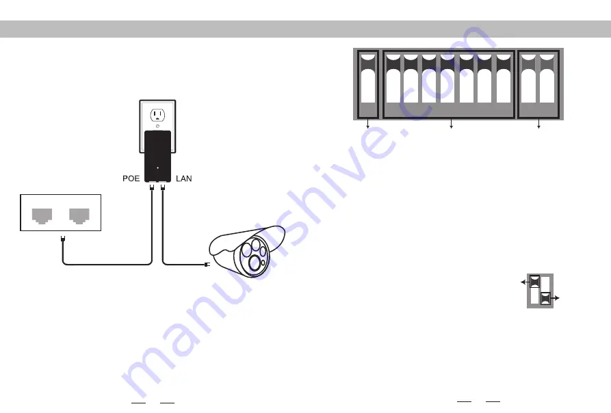
Connecting diagram PoE Power 

LAN1

LAN2

The bottom of the adapter has two RJ45 connections. One marked POE and one 

marked LAN.

Using one CAT5 cable(Network cable) , connect one end to ”LAN” and the other 

end to your camera,recorder, PC, etc. 

DIP device instructions

1

2 3

4

5

6

7

8

9 10

 Working Mode Key

Matching Key

IP Key

Up

Down

Button 1

 changes the mode of the device. UP is access point (AP) mode for use 

with your recorder, PC, etc.. DOWN is for use with your camera.

Button 2 through 8

 are for matching AP devices together. There are 128 various 

combinations that can be made from the 7 keys, which corresponds to 128 different 
SSIDs and 128 different segments.  The Pages 8-15 below shows all possible 
combinations.

Button 9 & 10

 are for point to multi-point functionality. To use up to 4 cameras 

with one recorder, configure the DIP switches as follows:
1.On the recorder/PC/Switch side, switches 9 and 10 should remain up.
2.On the camera side, select one of 4 configurations for switches 9 and 10:
a.Camera 1: 9 Down and 10 Down
b.Camera 2: 9 Down and 10 Up
c.Camera 3: 9 Up and 10 Down
d.Camera 4: 9 Up and 10 Up
3.You cannot duplicate the switch settings between Cameras for switches 9 & 10 or 
you will experience interference, thus the max of 4 points.

Remarks

1.Turn off the AP power before setting the button.
2.The SSID of DIP type AP defaults is not broadcast, password has been set up and 
can be customized.
3. Make sure the IP address of the camera is different from AP

Summary of Contents for DIP9526K-H

Page 1: ...e LAN connections 2 If you want to enter web page you need manually bound IP address of PC 3 The PoE power adapter has 3 inputs One is for the AC cord and two are for networking 4 Please note the PoE...

Page 2: ...different segments The Pages 8 15 below shows all possible combinations Button 9 10 are for point to multi point functionality To use up to 4 cameras with one recorder configure the DIP switches as f...

Page 3: ...following IP address Advanced OK Cancel NOTE The bound IP address of 5 8G is 172 19 0 2 Subnet mask is 255 255 0 0 Signal power setting Step 1 Manual disposes static IP address as it s shown in figur...

Page 4: ...cable to see if it is a cable problem 2 Change the wireless channel to avoid the signal interference Q A Transmit Power Configuration The default is the maximum value the transmit power should be red...

Page 5: ...n the signal is in the best condition Q9 How to reset the device A9 Long press the RST button for 6 seconds in the state of power on The dial up code corresponding to the text manual mode the network...

Page 6: ...5 No 46 No 47 No 48 5745 5765 5785 172 19 32 X 172 19 33 X 172 19 34 X 172 19 35 X 172 19 36 X 172 19 37 X 172 19 38 X 172 19 39 X 172 19 40 X 172 19 41 X 172 19 42 X 172 19 43 X 172 19 44 X 172 19 45...

Page 7: ...72 19 71 X 172 19 72 X 172 19 73 X 172 19 74 X 172 19 75 X 172 19 76 X 172 19 77 X 172 19 78 X 172 19 79 X 2 3 4 5 6 2 3 4 5 6 2 3 4 5 6 2 3 4 5 6 2 3 4 5 6 2 3 4 5 6 2 3 4 5 6 2 3 4 5 6 2 3 4 5 6 2 3...

Page 8: ...172 19 107 X 172 19 108 X 172 19 109 X 172 19 110 X 172 19 111 X 2 3 4 5 6 2 3 4 5 6 2 3 4 5 6 2 3 4 5 6 2 3 4 5 6 2 3 4 5 6 2 3 4 5 6 2 3 4 5 6 2 3 4 5 6 2 3 4 5 6 2 3 4 5 6 2 3 4 5 6 2 3 4 5 6 2 3 4...

Page 9: ...X 172 19 127 X 2 3 4 5 6 2 3 4 5 6 2 3 4 5 6 2 3 4 5 6 2 3 4 5 6 2 3 4 5 6 2 3 4 5 6 2 3 4 5 6 2 3 4 5 6 2 3 4 5 6 2 3 4 5 6 2 3 4 5 6 2 3 4 5 6 2 3 4 5 6 2 3 4 5 6 2 3 4 5 6 7 8 7 8 7 8 7 8 7 8 7 8 7...

Page 10: ...io frequency energy and if not installed and used in accordance with the instructions may cause harmful interference to radio communications However there is no guarantee that interference will not oc...

Page 11: ...the antenna types listed with the maximum permissible gain indicated Antenna types not included in this list having a gain greater than the maximum gain indicated for that type are strictly prohibited...

Reviews: