Toa N-8400RS Manual Download Page 8

8

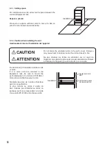
5.1.1. Setting space

For maintenance works, allow much space between the 

wall and Equipment rack.

Espace à prévoir 

Prévoyez  un  espace  suffisant  entre  le  mur  et  le  bâti  en 

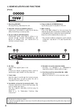
prévision des travaux de maintenance. 

N-8400RS

50 cm

50 cm

1 m

50 cm

Perforated panels

Equipment rack

N-8400RS

Bâti 

Panneau perforé

5.1.2. Caution when installing the unit

Avertissement lors de l’installation de l’appareil

Do not stack up 3 Substation interface units 

or more. 

If 2 or more units are mounted in the 

Equipment rack, be sure to mount the 

perforated panel of 1-unit size (PF-013B) or 

more above and below every 2 units.

N’empilez pas plus de 3 unités d’interface 

avec les sous-stations. 

Si vous montez au moins 2 unités en 

bâti,  n’oubliez  pas  d’installer  au  moins  un 

panneau perforé correspondant à la taille 

d’une unité (PF-013B) entre chaque unité.

Do not block the ventilation slots in the unit’s cover. Doing so 

may cause heat to build up inside the unit and result in fire.

CAUTION

Ne pas obstruer les fentes de ventilation sur le capot de 

l’appareil, sous peine de provoquer une accumulation de chaleur 

à l’intérieur de l’appareil, pouvant aboutir à un incendie. 

ATTENTION

Summary of Contents for N-8400RS

Page 1: ...ION MANUAL SUBSTATION INTERFACE UNIT N 8400RS Thank you for purchasing TOA s Substation Interface Unit Please carefully follow the instructions in this manual to ensure long trouble free use of your e...

Page 2: ...ting space 8 5 1 2 Caution when installing the unit 8 5 1 3 Mounting on the rack 9 5 2 Desk Top Installation 9 5 3 Wall Mounting 10 6 WIRING 11 6 1 Connection Diagram 11 6 2 Type of Cable 13 6 3 Relat...

Page 3: ...te the unit in this condition as this may cause fire or electric shock If you detect smoke or a strange smell coming from the unit If water or any metallic object gets into the unit If the power suppl...

Page 4: ...able de soutenir le poids de l appareil et de la patte de montage L appareil pourrait tomber et provoquer des blessures corporelles et ou des dommages mat riels Pendant l utilisation de l appareil En...

Page 5: ...ronment this product may cause radio interference in which case the user may be required to take adequate measures DESCRIPTION G N RALE L unit N 8400RS de TOA est l interface de sous station utilis e...

Page 6: ...nent expressed in 12 digit hexadecimal notation Rear 6 7 8 10 9 6 AC inlet Connect the supplied power cord Note If there is a danger of lightning strikes insert an appropriate surge arrester into the...

Page 7: ...supplied with the rack Note When installing the Blower unit and N 8400RS lay the equipment rack down face up to do installation work safely Since the Blower unit is installed from the inside of the r...

Page 8: ...unted in the Equipment rack be sure to mount the perforated panel of 1 unit size PF 013B or more above and below every 2 units N empilez pas plus de 3 unit s d interface avec les sous stations Si vous...

Page 9: ...the N 8400RS using the supplied machine screws Installation sur un bureau Pour installer l unit sur un bureau installez les pieds en plastique fournis sur le fond de l appareil l aide des vis fournies...

Page 10: ...it de l quipement et la fiche dispositif de d connexion doit tre facilement accessible N 8400RS Machine screw M3 x 6 supplied with the YC 850 Vis de m canique M3 x 6 fournie avec l unit YC 850 Wall su...

Page 11: ...efer to p 13 1 Power supply connection Connect the supplied power supply cord to AC Mains or a UPS Uninterruptible power supply About power supply cord handling The supplied power supply cord is desig...

Page 12: ...ez le cordon d alimentation fourni sur la prise secteur CA ou un syst me d alimentation sans interruption proposdumaniementducordond alimentation Le cordon d alimentation fourni est exclusivement dest...

Page 13: ...future expansion of the system Outdoor wires should be used where wiring passes through inaccessible areas such as attics or under floors where the maintenance is not performed Indoor wires may also b...

Page 14: ...Clipping tool Hook the end of the cable onto the terminal and with the cable end in hand press the YC 105 down onto the terminal from above Pressing down the YC 105 tool cuts off the excess cable end...

Page 15: ...aram trage du PC destin au service de maintenance 1 Prise amovible 4 broches 16 Pied en plastique 4 Vis de m canique M3 x 8 4 Pattes de montage 2 Vis taraud 3 x 8 8 Vis de montage en b ti 5 x 12 avec...

Page 16: ...checking the preparation date month and year shown at the lower right corner of the last page Example Prepared in September 2009 200909 Version update information Les fiches techniques des produits T...

Reviews: