7
3-4.
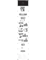
Mounting to an anchor bolt
Use the supplied ceiling reinforcement ring in
conjunction with the optional HY-AH1 Anchor
Hanging Bracket.
Note
Refer to the instruction manual included with the
HY-AH1 for the correct mounting procedure.
3-5.
Hanging from a ceiling suspension pipe (exposed installation)
Use the optional HY-BC1 Back Can.
Notes
• The supplied ceiling reinforcement ring is
not used.
• Refer to the instruction manual included
with the HY-BC1 for Back Can installation.
Suspension pipe
Speaker cable
HY-BC1 (optional)
Caution
Ensure that this length is
shorter than 53 mm (2
3
/
32
").
[Installed HY-BC1]
(Example of mounting to suspension pipe)
Step 4.
Attach a safety wire to prevent the speaker from accidentally falling.
To attach, tie one end of the supplied safety wire around the speaker's safety wire hook, and tie its
snap ring around a secure C-channel bar or suspension pipe.
[Flush ceiling mounting]
[Exposed mounting]
Safety wire
(accessory)
Safety wire hook
Speaker unit
Secure C-channel bar or
anchor bolt in the ceiling
Suspension pipe
Safety wire
(accessory)
Safety wire hook
Speaker unit
HY-BC1
(optional)
Anchor bolt
Ceiling panel
HY-AH1
(optional)
Ceiling reinforcement
ring (accessory)
[Installed HY-AH1]