Toa C-IF500 Instruction Manual Download Page 6

6

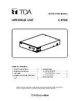
5.2. Connecting 32 or More Combination Cameras

Connect the Combination camera's control cable to the unit's Slave Connection Terminal, making sure to
match their polarities.

Remote controller
C-RM500

C-IF500

Combination

 camera

Combination

 camera

MASTER

SLAVE

GND

IN

GND

A

GND

B

GND

C

GND

D

GND

OUT

OFF

TERMINATION

ON

GND

Camera control terminal

Ch 1

Termination switch

OFF

Ch 2

Termination switch

OFF

Ch 31

Termination switch

ON

Ch 32

Termination switch

OFF

Ch 33

Termination switch

OFF

Ch 62

Termination switch

ON

Termination switch: ON

Shielded twisted-pair cable

[Connection cables]

• Recommended cable type: CPEV-S type (shielded twisted-pair cable) thicker than 0.65 mm in diameter.
• If multiple cameras are connected to a single terminal, the total of each cable distance between connected

equipment must be 1.2 km or less. 

[Termination switch setting]

• Set the unit's termination switch to ON when the unit and the C-RM500 Remote Controller are connected in

a matched pair in the system. 

• Make sure that the termination switches of the cameras connected to the system are set as follows.

Cameras other than the last connected camera: Termination switch OFF
Last connected camera:

Termination switch ON

Interface unit

C-IF500

Combination

camera

Combination

camera

Combination

camera

a

b

c

a + b + c     1.2 km

<

Interface unit

C-IF500

Combination

camera

Combination

camera

Combination

camera

Terminal switch

OFF

Terminal switch

OFF

Terminal switch

ON

Caution 
Up to 31 C-CC501, C-CC504, C-CC551, or
C-CC554 Combination Camera can be
connected to each Slave Terminal A-D. 

Summary of Contents for C-IF500

Page 1: ...TIONS Front 4 Rear 4 5 CONNECTIONS 5 1 System Examples 5 5 2 Connecting 32 or More Combination Cameras 6 5 3 Star Connection 7 6 SPECIFICATIONS 8 Please follow the instructions in this manual to obtai...

Page 2: ...the unit If they accidentally spill into the unit this may cause a fire or electric shock Do not insert nor drop metallic objects or flammable materials in the ventilation slots of the unit s cover a...

Page 3: ...lt in fire or electric shock When the Unit is in Use Do not place heavy objects on the unit as this may cause it to fall or break which may result in personal injury and or property damage In addition...

Page 4: ...used in the OFF position depending on the connection method Refer to p 6 for details 10 RS 232C terminal SLAVE RS 232C Converts the data received at the Master Connection Terminal into the RS 232C si...

Page 5: ...oller C IF500 5 5 CONNECTIONS 5 1 System Examples Example 1 Combination camera Monitor TV Multi switcher Remote controller C IF500 Example 2 Bottom TOA Corporation model C IF500 120 MADE IN JAPAN 12V...

Page 6: ...iameter If multiple cameras are connected to a single terminal the total of each cable distance between connected equipment must be 1 2 km or less Termination switch setting Set the unit s termination...

Page 7: ...ination switch ON Ch 2 Termination switch ON Ch 3 Termination switch ON Ch 4 Termination switch ON Ch 5 Termination switch ON Ch 6 Termination switch ON Ch 7 Termination switch ON Ch 8 Termination swi...

Page 8: ...PEV S cable thicker than 0 65 mm in diameter is used Optional Equipment MB 15B BK Rack mounting bracket for rack mounting one C IF500 unit MB 15B J Rack mounting bracket for rack mounting two C IF500...

Reviews: