
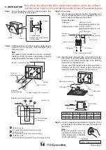

5. INSTALLATION
Step 1.
Pull out the baffle, unlatch 2 V-shaped springs, then
remove the baffle from the cabinet.
Step 3.
Make wiring.
3-1.
Insert the lead-in cables (cables from the amplifier) and
lead-out cables (cables to other speakers) into the
push-in connector attached to the cabinet.
[Applicable cable]
Solid wire:
ø0.8 to ø1.6 mm
(equivalent to AWG 20 – 14)
Stranded wire (7-core): 0.75 to 1.25 mm
2
(equivalent to AWG 18 – 16)
Step 4.
Hook 2 V-shaped springs attached to the baffle into the
slotted holes of the cabinet, then push the baffle onto
the cabinet.
Note
When the speaker mounting
orientation is vertical, pinch and
rotate the logo mark on the baffle
into the right position.
3-2.
Insert the fasten terminals fitted at the ends of both the
HOT (black) and COM (white) cables from the input
connector on the cabinet into the taps of the matching
transformer on the speaker unit.
Connect the COM (white) cable to the transformer's
COM tap, and the HOT (black) cable to the desired
transformer's input tap. (Refer to the figure below.)
Step 2.
Install the cabinet to the wall using the supplied tapping
screws 4 x 35. In this case, route the cables from a
cable entry hole.
Note
The speaker can be installed in a vertical or horizontal
orientation. Either concealed in-wall wiring or exposed
wiring are available for speaker cable connection.
Baffle
Cabinet
Baffle
V-shaped spring
Squeeze the spring to detach
from the cabinet.
Cabinet
From
the amplifier
To the matching transformer
9 mm
(0.35”)
COM (white)
COM (white)
HOT (black)
HOT (black)
Input connector
To the next
speaker
3.3kΩ
1.7kΩ
COM
6.7kΩ
13kΩ
HOT (black)
COM (white)
Matching transformer
Notches for exposed wiring
Screws for
horizontal mounting
Screws for
vertical mounting
Tapping screws 4 x 35 (accessory)
Cabinet
Input connector
[Cabinet mounting dimensions]
3-ø5 (0.2)
Unit: mm (in)
Cabinet outside
dimensions
83.5
(3.29)
250 (9.84)
83.5
(3.29)
190
(7.48)
Cable entry hole
(for exposed wiring at horizontal mounting)
Cable entry hole
(for concealed wiring at horizontal mounting)
Cable entry hole
(for concealed and exposed wirings at vertical mounting)
Impedance
1.7 k
Ω
3.3 k
Ω
6.7 k
Ω
13 k
Ω
100 V line
6 W
3 W
1.5 W
0.8 W
70 V line
3 W
1.5 W
0.8 W
0.4 W
Cabinet
Matching transformer
HOT (black)
COM (white)
Input connector
Baffle
533-06-158-10
URL: http://www.toa.jp/
TEI Rev1
Note: When mounting the BS-678 to plaster board walls be sure to use sufficient
"anchoring type" bolts from the local hardware store instead of the supplied screws.


