


7
6. CONNECTIONS
6.1. Removable Terminal Plug Connection
Notes
• Avoid soldering cable conductor, as contact resistance may increase when the cable is tightened and the
solder is crushed, possibly resulting in an excessive rise in joint temperatures.
• Use cables of AWG 12 – 24.
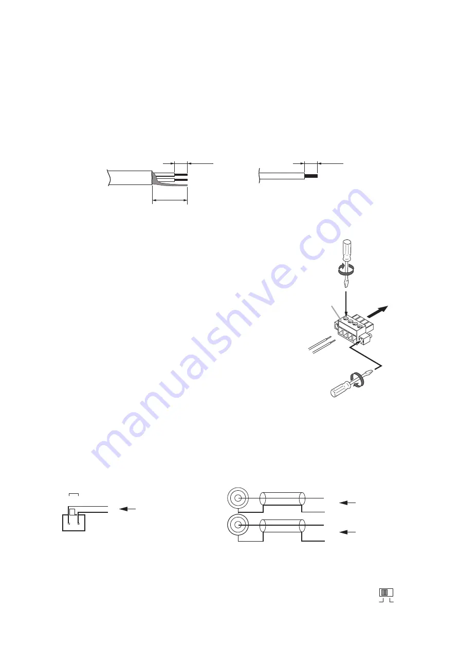
[Cable end treatment]
7 mm
7 mm
20 mm
2-core shielded cable
Solid cable and stranded cable
[Wiring Procedure]
Step 1.
Wiring the supplied removable terminal plug.
1-1.
Loosen the terminal screws to insert the wire.
1-2.
Tighten the terminal screws.
Ensure that the wire does not break free when pulled. If
the wire does pull free, repeat the connection procedure
from the start.
Step 2.
Insert the wired terminal plug into the corresponding
terminal block in the unit's rear panel.
Step 3.
Tighten the fixing screws. (Speaker output terminals only)
Notes
• Do not reverse
Steps 1
and
2
. Poor contact may result if force
is applied to the unit's internal circuit board pins while the
terminal screws are being tightened.
• Use an appropriate type screwdriver for terminal plug wiring.
Removable
terminal plug
1
2
3
Tighten
Tighten
6.2. Input Connections
6.2.1. Line input connections
LINE IN
H
E
E
H
Input source
Input source
Input source
H
E
H
E
Upper and lower RCA jacks are internally, passively mixed.
[Input level selection]
Input sensitivity can be switched to either 0 dB or +4 dB depending on the output level of the
input equipment.
INPUT
LEVEL
0dB
+4dB


