Toa 800D Series Operating Instructions Manual Download Page 8

8

1. Power switch

Press this switch to turn on the power. To turn off 

the power, press this switch again.
Note

The  power  switch  is  disabled  while  the  priority 

broadcast or the emergency broadcast is in progress.

2. Power indicator (Green)

Lights when the power is switched on and goes off 

when it is switched off.

3. Reset key

Press this key for 1 second or more to reset the 

unit.

Use a fine-tipped object to press in this switch.
Note

Perform the following steps before pressing the Reset 

key.

•  Turn  all  volume  knobs  fully  counterclockwise  to 

minimize the volume value.

•  Confirm  that  both  the  Priority  broadcast  indicator 

(9) and the Emergency broadcast indicator (10) are 

unlit.

•  Press the Power switch (1) to turn it OFF.

4. LED level meter (Green x 3, Orange x 1, Red x 1)

Displays the output level.

Adjust each volume control knob for an appropriate 

output  sound  so  that  the  red  indicator  does  not 

light.

Operating the unit while the red indicator remains 

lit causes the sound quality to degrade.

5. Error indicator (Red)

Lights  when  the  unit’s  internal  abnormality  has 

occurred.

  6. Overcurrent protection indicator (Red)

Lights  while  the  overcurrent  protection  circuit  is 

operating if overcurrent flows through the speaker 

output.

  7. Thermal protection indicator (Red)

Lights  while  the  thermal  protection  circuit  is 

operating.

  8. Network  connection  confirmation  indicator 

(Green)

An  indicator  to  identify  the  unit  using  a  web 

browser. 

•  Flashes  for  5  seconds  when  the  identification 

confirmation is performed using a web browser.

•  Flashes 3 times when the unit is started up. 

•  Lights when in the manual mode. 

( See  the  separate  setup  manual,  which  can  be 

downloaded from the TOA DATA Library (https://

www.toa-products.com/international/).)

  9. Emergency broadcast indicator (Red)

Lights  while  the  emergency  broadcast  is  in 

progress. 

( See  "PRIORITY  BROADCAST  FUNCTION"  on 

p. 22.)

 10. Priority broadcast indicator (Green)

Lights while the priority broadcast is in progress.

( See  "PRIORITY  BROADCAST  FUNCTION"  on 

p. 22.)

 11. CPU running indicator (Green)

Lights while the CPU is running.

 12. Volume control knobs for Inputs 1 through 6

Adjust the volume values of the Inputs 1 through 6. 

Rotate  each  knob  clockwise  to  increase  the 

volume value and counterclockwise to decrease it.

(See "VOLUME ADJUSTMENT" on p. 20.)

1

2

3

4

14

15

12

13

16

7

11

8

9

10

5

6

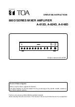
8. NOMENCLATURE AND FUNCTIONS

[Front]

The figure represents the A-812D.

Summary of Contents for 800D Series

Page 1: ...is manual to ensure long trouble free use of your equipment A 812D A 824D A 848D 800D SERIES MIXER AMPLIFIER The figure represents the A 812D Note on Firmware Upgrade Before using the device upgrade the firmware The latest firmware can be downloaded from the product page of the A 812D A 824D A 848D on the TOA Corporation website ...

Page 2: ... 16 9 6 Connecting to the Control Input Terminal 16 9 7 Connecting the External Equipment between the Pre amplifier Output and the Power Amplifier 17 9 8 Removable Terminal Plug Connection 18 10 SETTINGS 19 10 1 Chime Tone Setting 19 10 2 Module Setting 19 11 DUCKER DEPTH ADJUSTMENT 20 12 VOLUME ADJUSTMENT 20 13 INSTALLING TO AN EQUIPMENT RACK 21 14 CONTROL SETTINGS 21 15 PRIORITY BROADCAST FUNCTI...

Page 3: ...alifié Une maintenance s avère nécessaire si l appareil est endommagé au niveau du cordon d alimentation ou de la fiche a été mouillé par un liquide un objet est tombé à l intérieur s il a été exposé à la pluie ou l humidité s il ne fonctionne pas normalement ou s il est tombé 1 IMPORTANT SAFETY INSTRUCTIONS Read these instructions Keep these instructions Heed all warnings Follow all instructions ...

Page 4: ...f the power supply cord is damaged exposure of the core disconnection etc If it is malfunctioning no tone sounds To prevent a fire or electric shock never open nor remove the unit case as there are high voltage components inside the unit Refer all servicing to your nearest TOA dealer No objects filled with liquids such as vases shall be placed on the unit If they accidentally spill into the unit t...

Page 5: ...ause the connected speakers to heat resulting in a fire Contact your TOA dealer as to the cleaning If dust is allowed to accumulate in the unit over a long period of time a fire or damage to the unit may result If dust accumulates on the power supply plug or in the wall AC outlet a fire may result Clean it periodically In addition insert the plug in the wall outlet securely Switch off the power an...

Page 6: ...s Electronically balanced 4 microphone inputs MIC 1 to MIC 4 with Input setting switches Fine sound adjustment possible by connecting a signal processor like an equalizer between the pre amplifier output and the power amplifier input Bass and treble tone control knobs Output level meter Master volume control knob to simultaneously adjust all input levels Remotely controllable master volume Built i...

Page 7: ...to assign one of 8 priority levels to each broadcast content Use this function to make a complicated usage compared with the Ducker function such as to select the audio signal to mute For the details of the Priority broadcast function refer to PRIORITY BROADCAST FUNCTION on p 22 6 INSTALLATION PRECAUTIONS The supplied power supply cord is designed for exclusive use with the unit Never use it with ...

Page 8: ...protection indicator Red Lights while the overcurrent protection circuit is operating if overcurrent flows through the speaker output 7 Thermal protection indicator Red Lights while the thermal protection circuit is operating 8 Network connection confirmation indicator Green An indicator to identify the unit using a web browser Flashes for 5 seconds when the identification confirmation is performe...

Page 9: ...used 13 Volume control knobs for Module inputs 1 and 2 Adjust the volume values of the rear mounted modules Rotate each knob clockwise to increase the volume value and counterclockwise to decrease it 14 Bass control knob Rotate the knob clockwise to boost the bass and counterclockwise to cut it Setting the knob at the center makes the frequency characteristic flat 15 Treble control knob Rotate the...

Page 10: ...supply phantom power to the microphones connected to Inputs 3 and 4 25 Tip Phantom power is a 24 V DC 25 Input terminals Inputs 3 and 4 60 dB 600 Ω electronically balanced removable terminal block 3 81 mm 3 pins Input terminals dedicated for microphones 26 Input setting switches Inputs 1 and 2 Set the input sensitivity level LINE or MIC of the Inputs 1 and 2 27 When switched to the microphone inpu...

Page 11: ...erminal without using a hub 35 Recording output jacks 0 dB 600 Ω unbalanced type RCA jack x 2 Outputs the audio signals of the SUB output See BLOCK DIAGRAM on p 26 Used to record the broadcast contents by connecting the external recording device to these jacks 36 Pre amplifier output jack 0 dB 600 Ω unbalanced type RCA jack Used to input the same audio signal as a speaker output of the unit into a...

Page 12: ...on to 4 Ω terminal when the Impedance setting switch is set to 70 V Tip Recommended speaker cable is IV or HIV cable with thickness described below Solid copper cable ø0 32 2 0 mm Stranded copper cable 0 05 3 3 mm2 AWG 30 12 Low impedance connection Speaker output terminal A 812D 824D 848D 4 to 16 Ω High impedance connection Combined impedance 42 Ω A 812D 21 Ω A 824D 10 Ω A 848D 70 V line 70 V lin...

Page 13: ...orrect terminal according to the input terminal to use Inputs 1 through 6 Inputs 5 and 6 connections are for routing to AUDIO When connecting a 2 core shielded cable For cable wiring to the removable terminal plug refer to p 18 Inputs 5 and 6 for routing to DUCK When connecting a single core shielded cable Inputs 3 and 4 Inputs 1 and 2 Inputs 5 and 6 Removable terminal block Inputs 5 and 6 RCA Pin...

Page 14: ...IC PHANTOM ON 60 dB 600 Ω Inputs 3 and 4 Set whether or not to use phantom power on the Inputs 3 and 4 dedicated microphone inputs Phantom power when needed ON Phantom power when not needed OFF Factory preset A 812D 824D 848D Input specifications 60 dB 600 Ω electronically balanced Inputs 5 and 6 Set which to send the input audio signals to AUDIO or DUCK Operation when the Ducker function works is...

Page 15: ...aster volume control knob to the minimum position If set to the minimum no sound is output even if you maximize the volume level through this terminal See VOLUME ADJUSTMENT on p 20 A 812D 824D 848D Connectable volume controller 10 kΩ B taper potentiometer 9 4 Connecting to the Power Remote Control Output Terminal Use this terminal when remotely controlling other equipment This terminal is activate...

Page 16: ...ut withstand voltage 30 V DC or less current 25 mA or less 9 6 Connecting to the Control Input Terminal Priority broadcast can be controlled by inputting the contact signal to these terminals For the priority setting refer to the separate setup manual which can be downloaded from the TOA DATA Library https www toa products com international For cable wiring to the removable terminal plug refer to ...

Page 17: ...lifier section Pre amplifier output jack and the power amplifier section Power amplifier input jack Note Inserting a pin plug into the unit s power amplifier input jack disconnects the preamplifier section from the power amplifier section inside the unit IN OUT Signal processor A 812D 824D 848D Pre amplifier output specifications 0 dB 600 Ω unbalanced Power amplifier input specifications 0 dB 600 ...

Page 18: ...ls Conductor cross section area 0 05 3 3 mm2 0 08 2 0 mm2 AWG AWG 30 12 or equivalent AWG 28 14 or equivalent Solid cable and stranded cable Shielded cable 7 mm 2 7 mm 2 20 mm 0 28 0 28 0 79 2 Expose 8 mm 0 31 or more when using the above ferrule terminal and cut off an extra conductor protruding from the sleeve Note Avoid soldering stranded or shielded cable as contact resistance may increase whe...

Page 19: ...2 3 4 5 6 OFF ON 2 note ON OFF 1 2 3 4 5 6 OFF ON 1 note OFF ON 1 2 3 4 5 6 OFF ON Not used ON ON 1 2 3 4 5 6 OFF ON 10 2 Module Setting Set which to send the output from the module input to the AUDIO or DUCK using Switches 3 and 4 of the DIP switch See BLOCK DIAGRAM on p 26 A 812D 824D 848D OFF Output from the module input is sent to the DUCK ON Output from the module input is sent to the AUDIO ...

Page 20: ...s 1 and 2 volume control knobs Software master volume control Remote master volume control Master volume control knob Master volume control knob Remote master volume control Software master volume control Input 1 Volume control knob Module input 2 Volume control knob If any one of the volume controls is set to the minimum no sound is output even if other volume control is set to the maximum If you...

Page 21: ...ngs of 1 unit size or greater is mounted over and under each unit as well as on the top and at the bottom of the rack 14 CONTROL SETTINGS Output levels are adjustable with individual volume controls For music play or announcements adjust the corresponding volume control so that the red indicator doesn t light Note that the sound quality is downgraded when the red indicator remains lit To prevent t...

Page 22: ...ed audio signals can be muted in the case of normal broadcast that is not activated by any trigger For details refer to the separate setup manual which can be downloaded from the TOA DATA Library https www toa products com international Item Setting contents Valid Invalid When set to Valid priority broadcast will start if the corresponding trigger is input Priority level You can set 8 different le...

Page 23: ...to emergency broadcast 15 4 Normal Broadcast The broadcast that stays in the state where the unit s power is ON with no trigger input is referred to as the Normal broadcast Note Chime at normal broadcast cannot be set to ON 15 5 Relationship between the Priority Emergency Broadcasts and the Power On Off State When this unit is in power OFF state This unit is turned ON when the Priority or Emergenc...

Page 24: ...t starts up in Standard mode Shown below are the operations by the factory default Operation image Normal broadcast Control input 1 Control input 2 Control input 3 Control input 4 Broadcast state OPEN CLOSED OPEN CLOSED OPEN CLOSED OPEN CLOSED Any broadcast not muted Chime sounds and any broadcast not muted Chime not sound only Audio input 1 is broadcast muting other inputs Broadcast by the Contro...

Page 25: ...tes and other countries Google Chrome is the trademark of Google LLC in the United States and other countries Mozilla and Firefox are the trademarks of The Mozilla Foundation in the United States and other countries 2 If the volume value is set to the minimum on this screen no sound is output even if you set the unit s front mounted volume control knobs to the maximum position Also the volume valu...

Page 26: ...ute Mute Mute RESET CHIME MODULE 1 MODULE 2 EMERGENCY Change INPUT1 20 dB 600 Ω LINE 60 dB 600 Ω MIC INPUT2 20 dB 600 Ω LINE 60 dB 600 Ω MIC INPUT3 60 dB 600 Ω MIC INPUT4 60 dB 600 Ω MIC INPUT5 AUDIO 60 dB 600 Ω MIC INPUT5 DUCK 20 dB 10 kΩ LINE INPUT6 DUCK 20 dB 10 kΩ LINE MODULE 1 20 dB 10 kΩ LINE INPUT6 AUDIO 60 dB 600 Ω MIC 24 V 24 V 24 V 24 V PRE AMP OUT 0 dB 600 Ω PWR AMP IN 0 dB 600 Ω REC OU...

Page 27: ...ble Module 1 2 AUDIO DUCK selectable Audio Output SPEAKER OUT High impedance 70 V line 42 Ω Low impedance 4 to 16 Ω selectable High impedance 70 V line 21 Ω Low impedance 4 to 16 Ω selectable High impedance 70 V line 10 Ω Low impedance 4 to 16 Ω selectable removable terminal block 5 00 mm 3 pins REC OUT 0 dB 600 Ω unbalanced RCA pin jack x 2 PRE AMP OUT 0 dB 600 Ω unbalanced RCA pin jack Control I...

Page 28: ...the unit unless expressly approved by TOA Electronics Inc could void your authority to operate the equipment DECLARATION OF CONFORMITY TOA Electronics Inc 1 Harmon Plaza Suite 602 Secaucus New Jersey 07094 USA TEL 650 452 1200 declare under our sole responsibility that the product 800D SERIES MIXER AMPLIFIER A 812D 3CU A 824D 3CU A 848D 3CU comply with Part 15 of FCC Rules Operation is subject to ...

Reviews: