▶
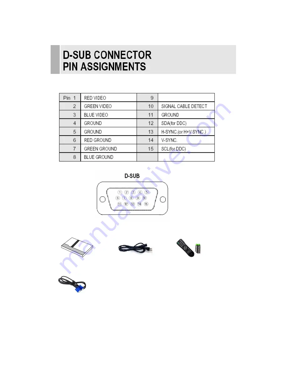
PIN ASSIGNMENTS
ACCESSORY
INSTRUCTION MANUAL
……………………………………………………………………………
22
2. Power Cord
1. User’s Manual
3. Remote Control Unit
And Battery
4. VGA Cable
Page 1: ...15 INCH PREMIUM TFT LCD CCTV MONITOR 15RTC INSTRUCTION MANUAL Please read this manual thoroughly before use and keep it handy for future reference ...
Page 2: ...autions 3 CAUTIONS 4 FCC RF INTERFERENCE STATEMENT 5 CONNECTING WITH EXTERNAL EQUIPMENT 6 REMOTE FUNCTIONS 7 CONTROLS AND FUNCTIONS 8 20 MOUNTING GUIDE 21 D SUB CONNECTOR PIN ASSIGNMENTS 22 POWER MANAGEMENT 23 SPECIFICATIONS 24 TROUBLESHOOTING GUIDE 25 1 INSTRUCTION MANUAL ...
Page 3: ...tlet consult an electrician for replacement of the obsolete outlet 10 Protect the power cord from being walked on or pinched particularly at plugs convenience receptacles and the point where they exit from the apparatus 11 Only use attachments accessories specified by the manufacturer 12 Use only with the cart stand tripod bracket or table specified by the manufacturer or sold with the apparatus W...
Page 4: ...apparatus shall not be exposed to dripping or splashing and no objects filled with liquids such as vases shall be placed on the apparatus This symbol is intended to alert the user to the presence of uninsulated dangerous voltage within the product s enclosure that may be of sufficient magnitude to constitute arisk of electric shock to persons This symbol is intended to alert the user to the presen...
Page 5: ...o rain or moisture This unit is designed to be used in the office or home Do not subject the unit to vibrations dust of corrosive gases KEEP IN A WELL VENTILATED PLACE Ventilation holes are provided on the cabinet to prevent the temperature from rising Do not cover the unit or place anything on the top of unit AVOID HEAT Avoid placing the unit in direct sunshine or near a heating appliance TO ELIM...
Page 6: ...g the equipment off and on the user is encouraged to try to correct the interference by one or more of the following measures Reorient or relocate the receiving antenna Increase the separation between the equipment and receiver Connect the equipment into an outlet on a circuit different from that to which the receiver is connected Consult the dealer or an experienced radio TV technician for help O...
Page 7: ...IN Composite signal Input for AV2 6 VIDEO 2 AV2 OUT Video looping output for AV2 7 AUDIO 1 IN Stereo Audio Signal Input This input is for AV1 S VIDEO 8 AUDIO 2 IN Stereo Audio Signal Input This input is for AV2 9 S VIDEO Y C IN Y C separated signal input 10 S VIDEO Y C OUT Y C separated signal looping output 11 PC STEREO IN INSTRUCTION MANUAL 6 1 2 3 4 5 6 7 8 9 10 11 ...
Page 8: ...elect AV1 mode 6 AV2 Select AV2 mode 7 S VIDEO Select S VODEO mode 8 PC Select PC mode 9 AUTO Auto geometry adjustment in PC Source 10 MUTE Mute the sound 11 MENU Activates and exits the On Screen Display 12 EXIT Exit the On Screen Display 13 VOL Increases or decreases the level of audio volume 14 UP DOWN Move to OSD menu 15 ENTER Accepts your selection or displays the current mode 16 INFO Input m...
Page 9: ...IT Activates and exits the On Screen Display 7 POWER ON OFF Turns the power ON or OFF There will be a few seconds delay before the display appears 8 IR Sensor Remote controller sensor 9 POWER LED The power LED next to the power switch lights with green when the power is turned ON The power is turned off by pressing the power switch again and the power LED goes Red INSTRUCTION MANUAL 8 8 9 1 2 3 4 ...
Page 10: ... right button to adjust picture setting Press the MENU button to save Brightness Increase or decrease the intensity of the image Contrast Increase or decrease the intensity lightness or dimness of the image Color Increase or decrease the colour of the picture Tint Increase or decrease the tint of the picture Sharpness Increase or decrease the sharpness of the picture 9 INSTRUCTION MANUAL ...
Page 11: ...mode Press the MENU button and then up down button to select the Custom menu Press the up down button to select Custom sub menu Press right button to adjust picture setting Press the MENU button to save INSTRUCTION MANUAL 10 ...
Page 12: ...tton to select the Picture Sound Press the right or ENTER button 1 Picture Mode Press the up down button to select the Picture Mode Press the right or ENTER button and then press up down button to select the desire Picture Mode Press the MENU button to save 11 INSTRUCTION MANUAL ...
Page 13: ...2 Color Tone Press the up down button to select the Color Tone Press the or ENTER button and then up down button to select the desired color tone Press the MENU button to save INSTRUCTION MANUAL 12 ...
Page 14: ...3 Mute Press the up down button to select the Mute Press the or ENTER button and then up down button to select the desired Mute Press the MENU button to save 13 INSTRUCTION MANUAL ...
Page 15: ...s the up down button to select the Volume Press right button to adjust Volume Press the MENU button to save 5 PC Only PC mode Press the up down button to select the PC Press the or ENTER button INSTRUCTION MANUAL 14 ...
Page 16: ...eometry adjustment Phase Adjust the number of horizontal picture elements H position Move image horizontally on screen right or left V position Move image vertically on screen up or down Frequency Adjust the vertical noise of screen image C SETUP MENU Press the MENU button and then up down button to select the Setup menu Press the right or ENTER button 15 INSTRUCTION MANUAL ...
Page 17: ...1 Reset Press ENTER button to select the reset Reset Select to reset all setting to the factory default values INSTRUCTION MANUAL 16 ...
Page 18: ...2 Language Press the up down button to select the Language menu Press the right or ENTER button Press the up down button to select language Press the MENU button to save 17 INSTRUCTION MANUAL ...
Page 19: ...3 OSD Tone Press the up down button to select the OSD tone menu Press the right or ENTER button Press the up down button to select the desire OSD Tone Press the MENU button to save INSTRUCTION MANUAL 18 ...
Page 20: ...4 Blue Screen Press the up down button to select the blue screen Press the right or ENTER button Press the up down button to select on or off Press the MENU button to save 19 INSTRUCTION MANUAL ...
Page 21: ...5 Key Lock Press the up down button to select the key lock menu Press the right or ENTER button Press the up down button select on or off Press the MENU button to save INSTRUCTION MANUAL 20 ...
Page 22: ...the LCD monitor to the mounting bracket using the optional mounting bracket sold separately Wall mount Installation 1 Remove the monitor stand bracket assembled with monitor 2 Install the mounting bracket to the monitor using the screws provided with the mounting bracket 21 INSTRUCTION MANUAL ...
Page 23: ... PIN ASSIGNMENTS ACCESSORY INSTRUCTION MANUAL 22 2 Power Cord 1 User s Manual 3 Remote Control Unit And Battery 4 VGA Cable ...
Page 24: ...CONSUMPTION MODE POWER CONSUMPTION ON 36W STANDBY 11W SUSPEND 11W ACTIV OFF 8 5W LED INDICATOR The power management feature of the monitor is comprised of four stages On Green Standby Suspend Active off Red on off 1 sec and Unsupported mode Green MODE LED COLOR MONITOR OPERATION ON GREEN Normal Operation STANDBY SUSPEND ACTIV OFF RED ON OFF 1 SEC Screen blanks after preset idle time And some elect...
Page 25: ... 75Ω terminated loop through out SYNC Separate TTL Level S VIDEO 1ch input Y C loop through out AV composite Sound in PC Stereo in ACTIVE DISPLAY AREA W x H 304 1 mm x 228 1 mm PACKING DIMENSIONS W x D x H 440mm X 160mm X 390mm 17 3 x 6 3 x 15 4 WEIGHT Net Weight 4 8Kg 10 6Ibs Gross Weight 6 26Kg 10 6Ibs POWER SUPPLY Electrical Ratings DC 12V 3A AC110 220V 50 60HZ for Auto switching NOTE Technical...
Page 26: ... possible harm to the environment or human health from uncontrolled waste disposal please separate this from other types of wastes and recycle it responsibly to promote the sustainable reuse of material resources Household users should contact either the retailer where they purchased this product or their local government office for details of where and how they can take this item for environmenta...