background image


172-65288MA-02  (SW1U-A/SW1U-B)  6 Feb 2019


5


Checking the Piping 


Use only under conditions in which no water hammer will occur. The 

impact of water hammer may damage the product, leading to fluid 

discharge, which may cause burns or other injury.


CAUTION 


Check to make sure that the pipes to be connected to the trap have been installed 
properly. 

1.  Is the pipe diameter suitable? 
2.  Is the piping where the trap is to be installed horizontal? 
3.  Has sufficient space been secured for maintenance? 
4.  Have isolation valves been installed at the inlet and outlet? If the outlet is subject 

to back pressure, has a check valve been installed? 

5.  Has a bypass line been installed properly? 
6.  Is the inlet pipe as short as possible, with as few bends as possible, and installed 

so the liquid will flow naturally down into the trap? 


Operation 


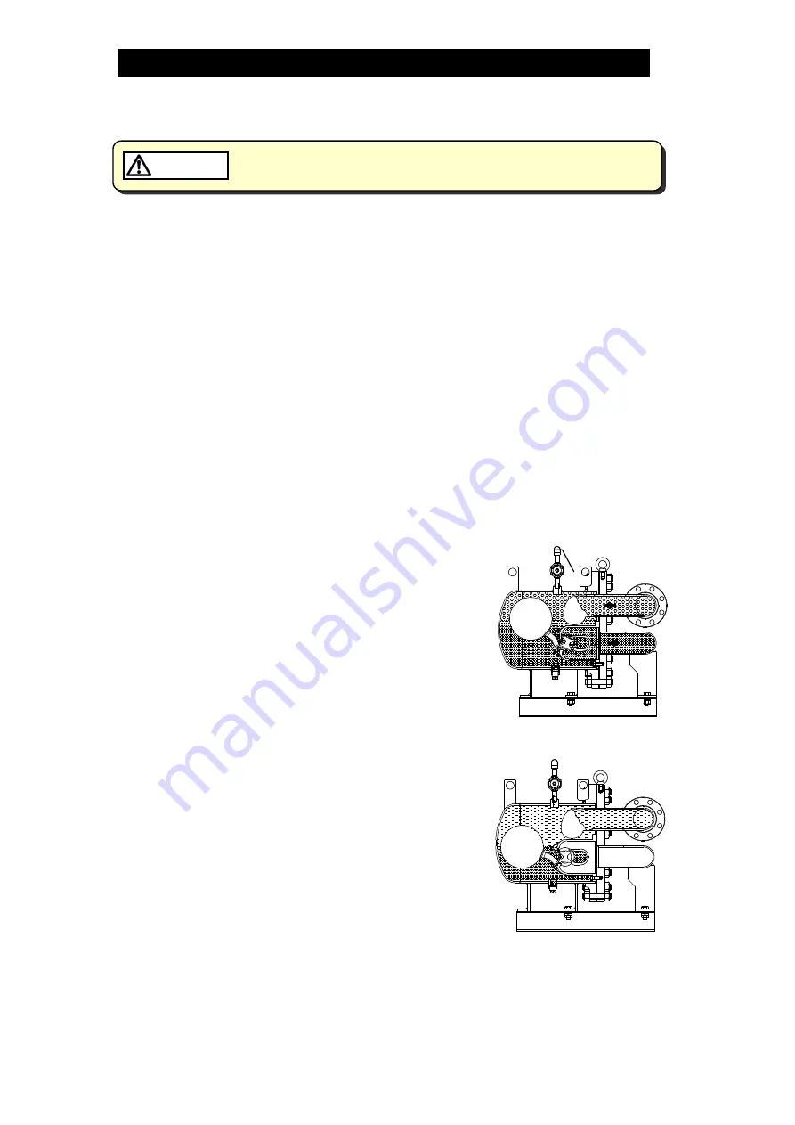
Principles of condensate discharge: 


At start-up, open the bypass valve to remove any initial 
condensate or air at 100

°

C (212

°

F) or less. 

(This step must be performed in order to ensure 
smooth start-up.) 
 
Air binding occurs when the inflow of steam is 
accompanied by the inflow of air during normal 
operation. Whenever air binding occurs, it can be 
released by opening the bellows sealed valve to 
discharge the air. 
 
After air is discharged, the bellows sealed valve must 
be closed. 
 
As condensate flows into the trap, the rising 
condensate level causes the float to rise due to 
buoyancy, automatically opening the valve and 
allowing condensate to be continuously discharged. 
When this occurs, the opening size of the valve varies 
depending on the condensate flow rate. 
 
As the condensate is discharged, the condensate level 
falls, causing the float to fall, thereby automatically 
closing the valve. 
 
The valve remains closed as long as no condensate 
enters the trap.


Bellows Sealed 
Valve


Summary of Contents for SW1U-A

Page 1: ...172 65288MA 02 SW1U A SW1U B 6 February 2019 Process Lever Float Steam Trap SW1U A SW1U B Copyright 2019 by TLV CO LTD All rights reserved ...

Page 2: ...U B 6 Feb 2019 1 Contents Introduction 2 Safety Considerations 3 Checking the Piping 5 Operation 5 Specifications 6 Configuration 7 Installation 8 Maintenance 10 Disassembly Reassembly 11 Troubleshooting 12 Product Warranty 13 ...

Page 3: ...d by the pressure differential between inlet and outlet pressures are balanced a four bladed valve ensures stable trap operation at all times This trap is ideal for applications requiring the removal of condensate from equipment using large quantities of steam and from process machinery Additionally it quickly and automatically discharges large quantities of condensate at a temperature slightly lo...

Page 4: ...ndicates a DANGER WARNING or CAUTION item DANGER Indicates an urgent situation which poses a threat of death or serious injury WARNING Indicates that there is a potential threat of death or serious injury CAUTION Indicates that there is a possibility of injury or equipment product damage WARNING NEVER apply direct heat to the float The float may explode due to increased internal pressure causing a...

Page 5: ...to discharge of fluids causing burns other injuries or damage Be sure to use only the recommended components when repairing the product and NEVER attempt to modify the product in any way Failure to observe these precautions may result in damage to the product and burns or other injury due to malfunction or the discharge of fluids Use only under conditions in which no freeze up will occur Freezing ...

Page 6: ...own into the trap Operation Principles of condensate discharge At start up open the bypass valve to remove any initial condensate or air at 100 C 212 F or less This step must be performed in order to ensure smooth start up Air binding occurs when the inflow of steam is accompanied by the inflow of air during normal operation Whenever air binding occurs it can be released by opening the bellows sea...

Page 7: ...use this product in excess of the maximum operating pressure differential such use could make discharge impossible blocked CAUTION Use only under conditions in which no freeze up will occur Freezing may damage the product leading to fluid discharge which may cause burns or other injury CAUTION Refer to the product nameplate for detailed specifications Maximum Allowable Temperature TMA Model Valve ...

Page 8: ...te 3 Valve Seat Body 13 Cover Gasket 23 Mounting Bolt 4 TLY Valve 14 Cover Bolt 24 Mounting Nut 5 Float Unit 15 Cover Nut 25 Spring Washer 6 Seal Ring 16 Baffle 26 Washer 7 Bearing 17 Valve Seat Body Bolt 27 Foundation Bolt 8 Valve Holder 18 Drain Plug 28 Set Screw 9 Valve Holder Bolt 19 Mounting Base 29 Eye Bolt 10 Lever Bolt 20 Wave Spring A A Cut View SW1U A A A Cut View SW1U B ...

Page 9: ...re to install a bypass line At start up open the bypass valve to remove initial condensate and air of less than 100 C 212 F 3 Install an inlet valve and strainer at the trap inlet 4 Before installing the product open the inlet valve and blow out the piping to remove any piping scraps dirt and oil Close the inlet valve after blowdown 5 Install an outlet pipe with consideration for maintenance work ...

Page 10: ...172 65288MA 02 SW1U A SW1U B 6 Feb 2019 9 SW1U A SW1U B Units mm in 41 5 16 49 3 16 7 7 8 9 7 8 63 53 1 8 Install outlet pipe for air discharge to the safe place ...

Page 11: ...t may cause damage to piping and equipment resulting in faulty or low quality products or losses due to steam leakage Normal Condensate is discharged continuously together with flash steam and the sound of flow can be heard If there is very little condensate there is almost no sound of flow Blocked Discharge Impossible No condensate is discharged The trap is quiet and makes no noise and the surfac...

Page 12: ...sembly Reassembly Part During Disassembly During Reassembly Bellows Sealed Valve Slowly open before disassembling the trap and make sure no remained pressure in the trap Close after reassembling the trap Body Unit Loosen and remove the cover nuts and bolts connecting the body unit and cover unit Consult the table of tightening torques and tighten cover nuts to the proper torque Cover Gasket Remove...

Page 13: ... until the internal pressure equals atmospheric pressure and the surface of the product has cooled to room temperature Disassembling or removing the product when it is hot or under pressure may lead to discharge of fluids causing burns other injuries or damage CAUTION When the product fails to operate properly use the following table to locate and cause the remedy Problem Cause Remedy No condensat...

Page 14: ...mproper installation use handling etc by other than TLV CO LTD authorized service representatives 2 Malfunctions due to dirt scale rust etc 3 Malfunctions due to improper disassembly and reassembly or inadequate inspection and maintenance by other than TLV CO LTD authorized service representatives 4 Malfunctions due to disasters or forces of nature 5 Accidents or malfunctions due to any other caus...

Reviews: