background image


Contents 

1.0 

 Warnings .................................................................................................................................. 3 

1.0.1 

 Read Me .................................................................................................................................. 3 

1.0.2 

 Power ...................................................................................................................................... 4 

1.0.3 

 IP Rating .................................................................................................................................. 4 

2.0 

 Installation...................................................................................................................................... 4 

2.0.1 

 Location ................................................................................................................................... 4 

2.0.2 

 Fixings ...................................................................................................................................... 4 

2.0.3 

 Power ...................................................................................................................................... 4 

2.0.4 

 Data ......................................................................................................................................... 5 

2.0.4.1 - DMX .................................................................................................................................. 5 

2.0.4.2 - Connectors ........................................................................................................................ 5 

2.0.5 

 LED Connections...................................................................................................................... 5 

2.0.5.1 

 Correct Procedure ............................................................................................................ 5 

2.0.5.2 

 Short Circuit Error ............................................................................................................ 5 

3.0 

 User Interface Settings ................................................................................................................... 5 

3.0.1 

 accessing the UI....................................................................................................................... 5 

3.0.2 

 System Modes ......................................................................................................................... 6 

3.0.3 

 Changing the DMX address ..................................................................................................... 6 

3.0.4 

 Changing the LED mode (RGBW/RGB, CCT) ............................................................................ 6 

3.0.5 

 Macro Modes & DMX settings ................................................................................................ 6 

3.0.6 

 Sound Modes & Settings ......................................................................................................... 7 

3.0.7 

 Auto Modes & Settings ........................................................................................................... 7 

3.0.8 

 Manual Mode .......................................................................................................................... 7 

4.0 UI Illumination ................................................................................................................................... 7 

4.0.1 Display Illumination Settings ...................................................................................................... 7 


Summary of Contents for DCV-300

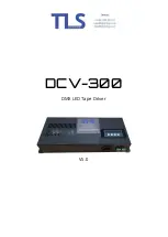
Page 1: ...DCV 300 DMX LED Tape Driver V5 0...

Page 2: ...Connections 5 2 0 5 1 Correct Procedure 5 2 0 5 2 Short Circuit Error 5 3 0 User Interface Settings 5 3 0 1 accessing the UI 5 3 0 2 System Modes 6 3 0 3 Changing the DMX address 6 3 0 4 Changing the...

Page 3: ...ply Do not switch the equipment on and off in short intervals as this will reduce the system s life Only use the equipment indoors Do not expose to flammable sources liquids or gases Always disconnect...

Page 4: ...e terminals evenly to ensure the phoenix connector do not burn out 1 0 3 IP Rating The DCV300 is IP20 rated and must be used indoors and in a dry environment 2 0 Installation 2 0 1 Location Please ens...

Page 5: ...ment The common positive load should be split across the two common terminals on the DCV 300 to avoid damaging the connector You can connect a maximum of 150W per common terminal 2 0 5 2 Short Circuit...

Page 6: ...GB CCT Cycle menu until the display reads System Mode and press enter Once you have accessed this screen the display will show a two digit and a three digit number the first two digit number shows the...

Page 7: ...trolled in UI 3 RGBW fade with Dim Speed control controlled in UI 4 RGBW Step with Dim Speed control controlled in UI 3 0 8 Manual Mode For manual output control 1 Dim Output 1 controlled in UI 2 Dim...

Page 8: ...For installation and technical support please contact us on 01603 295 011 or email info tlspixelite co uk or visit www tlspixelite com TLSPixelite Limited all rights reserved...

Reviews: