background image


63 
 

14.7


72000204 - Orion with kpSensor bus 


Summary of Contents for KEYPROCESSOR Orion

Page 1: ...1 Pluto Orion Doc no 01052018 Modular controller line Installation instructions ...

Page 2: ... 3 2 Required software versions 9 3 3 Connections 10 3 4 Status LED 10 3 5 Support in offline situation 10 4 Pluto connection options 12 4 1 Connecting with Orion 12 4 2 Serial connection RS 232 13 5 Maintenance page Pluto 14 5 1 Network settings 14 6 Orion 16 6 1 Applications 16 6 2 Required software versions 16 6 3 Functions and support 16 6 3 1 Orion connected to the Pluto 16 6 3 2 Orion RS485 ...

Page 3: ...r 42 10 2 2 2 Multiple Orions on a single data line bus 44 11 How to 46 11 1 Installation Pluto 46 11 2 New Orion on existing Pluto 47 11 3 New RS485 reader on existing Orion 47 11 4 New Orion on existing Polyx 48 11 5 Replace Polyx for Pluto and Orion 48 11 6 Replace Polyx 2x kpBus for Pluto and two Orions 49 11 7 Replace iPU 8 for a Pluto with four Orions 50 11 8 Pluto Make factory default 50 11...

Page 4: ...4 ...

Page 5: ... with Orions with Pluto 23 Figuur 14a Connecting with Orions kpBus 23 Figure 15 Polyx with RS485 card reader 24 Figure 16 Pluto with RS485 card reader 24 Figure 17 Orion with Clock data Wiegand reader 25 Figure 18 Pluto Orion kpBus 27 Figure 19 Pluto Orion kpBus with Clock data Wiegand and RS485 reader 28 Figure 20 Polyx kpBus 29 Figure 21 Polyx kpBus with Clock data Wiegand and RS485 reader 29 Fi...

Page 6: ...instruction manual covers the entire range of Keyprocessor modular controllers One or more software versions are specified in every module related chapter These versions are important when it comes to support for the product ...

Page 7: ...g Place the modular controller against the rail and click it into place Mounting the modular controller onto the rail NOTE For every modular controller note the location serial number and or MAC address of the device This information can be found on top of the device just below the LED Figure 1 Mounting controller ...

Page 8: ...needed The power supply must conform to SELV directives 2 3 Stacking connector The modular controller is fitted with a stacking connector terminal on either side This connector links together both the power and the communication feeds between the modular controllers Sections 4 1 and 7 1 specify specific conditions for the use of this connector Operation The supplied stacking connector must be inse...

Page 9: ...ation the Pluto can be used in a range of different ways The Pluto can be used if More flexibility is required More redundancy is required End to End security is required Maximum security is required 3 2 Required software versions In order to guarantee optimum performance the following software versions are required Version Supported iProtect Support Linux Ubuntu 16 04 8 04 Rootfs V4 22 ...

Page 10: ... data storage is necessary including cards with valid access rights And in this offline situation the events of inputs lock control outputs and cards may not be lost Port Description A USB 2 0 port x2 B Stacking connector for Orions C Status LED D Power input E USB OTG console port F Network port G Stacking terminal for future use Port C Colour of the LED Description Blue No connection Red No acti...

Page 11: ...11 The maximum numbers are described in the table below Pluto storage FIFO Nr Description Maximum per Pluto 1 Cards with valid access rights 50 000 2 Events 50 000 ...

Page 12: ...inserting stacking connectors always ensure the power is off depending on the power feed being used at least 75W a maximum of four Orions can be interconnected to one another to the left of the Pluto using the stacking connector see Figure 3 Stacking connector if the stacking connector is used to supply the Orions with power and the door controllers collectively draw more power than 50W the C GND ...

Page 13: ...onnection in series is preferred a USB to RS232 converter recommended by Keyprocessor part number 503 1805 must be used Only one USB to RS 232 converter can be used per Pluto See chapter 14 5 Rear USB RS 232 Figure 7 Pluto serial connection ...

Page 14: ...ogin screen Once the right username and corresponding password have been entered the system status page will be displayed Default login Username controller Password Pluto The following page is displayed NOTE When iProtect connects to the Pluto the default password will expire The new login password will be displayed in the iProtect line in the admin page 5 1 Network settings Network settings e g I...

Page 15: ...15 Once saved the new settings will take immediate effect and the Pluto will only be accessible using the new IP address ...

Page 16: ... kpBus communication calamity card SD card Sirius Pincode based on Clock data Wiegand protocol NO NC output behavior provisioning connection to Pluto 8 04 6 3 Functions and support Depending on the desired application of the Orion a range of functions are available Below is a list of functions 6 3 1 Orion connected to the Pluto Type of controller connected Pluto Number Connection Digital input 2 T...

Page 17: ...surement reader Yes Power consumption readers Yes H1 and H2 overload detection Yes 6 3 3 Orion functional replacement for the Orbit reader Type of controller connected iPU 8 Polyx or Pluto Number Connection Digital input 8 A1 A2 A3 A4 A5 A6 T1 T2 Digital output 4 H1 H2 O2 O5 Wiegand ABA card reader 2 LD D0 D1 C and V Status LED Yes RJ45 PRT1 RS422 communication with controller Indoor temperature s...

Page 18: ...n and the method of connection Port Description A PRT1 B Reader 1 C IO 1 D Power input E Status LED F MicroSD slot G End of line jumper H Stacking connector I RS485 and kpSensor bus J Reader 2 K IO 2 L PRT2 H E B C A D H F G PRT1 E G F H L K J I H PRT2 Figure 9 Orion connections rear Figure 8 Orion connections front ...

Page 19: ...ide card reader A2 Monitored input 2 LD Card reader LED operation A3 Monitored input 3 D0 DO Data or Digital input C Digital ground D1 D1 Clock or Digital input H1 High Power output 1 O1 Digital output 1 C Digital ground C GND digital ground O2 Digital output 2 V Power feed card reader O3 Digital output 3 Connector D Description Earth ground GND digital ground Orion power input 12 24VDC T Tamper i...

Page 20: ...ow table Port D Colour of the LED Description Light blue Bootloader Connecting to iProtect Checking MD5 Blue Bootloader Starting Blue Bootloader Programming firmware Or violet Pink Bootloader No valid application to start Pink Application Format SD card Orange Application Checking SD card initialisation Green Application Calamity mode Red Application When using no SD card the LED will flash red if...

Page 21: ...correctly could cause serious damage to the Orion or SD card 6 6 2 Calamity cards Calamity cards are cards that need access to a door s when there is no communication with the Network Controller offline In an offline situation the Orion will function fully independently If a user has a calamity priority which is created within iProtect in the card dialog there will be no noticeable issues for the ...

Page 22: ...r 2 5 A5 Push button 6 T2 Emegency door release The following table shows all the outputs Outputs Nr Connection Description Reader nr Invert NO NC 1 H1 Door lock Reader 1 Yes 2 O1 Output 3 O2 Alarm 4 O3 Output 5 H2 Door lock Reader 2 6 O4 Output 7 O5 Alarm 8 O6 Output The following table shows the reader Reader Nr Description Protocol Kaartdata interpretation Pincode function offline 1 Reader 1 Cl...

Page 23: ...power and the door controllers collectively draw more than 2A the C GND on the last Orion beside the High Power output must be separately wired to the power supply When connecting Orion s to a Pluto the kpBus should not be connected externally See figure 13 When linking only Orions the kpBus must be connected externally See figure 13a Figure 13 Connecting with Orions with Pluto Front PRT2 Orion 4 ...

Page 24: ...ion between cards and the system can be secured by means of AES encryption When the maximum of four Orions are connected to a Pluto see figure 13 a maximum of eight RS485 card readers can be connected 7 2 1 1 Connection of RS485 card reader PRT1 A 2 L TIA EIA 568 B Sirius i serie Nr Description Wire color Sticker Description 1 B White Orange 2 B 2 A Orange 1 A 3 B Z White Green 2 B 4 12Vdc Blue Vc...

Page 25: ...der 7 2 2 Clock data Wiegand card reader In virtually all configurations you have the option of connecting a Clock data Wiegand card reader to either side of the Orion except if an RS485 card reader is connected It is not possible to connect a second card reader to any one side of the Orion N PRT2 Clock data Wiegand Orion Pluto USB PRT1 Clock data Wiegand Front Rear J B Figure 17 Orion with Clock ...

Page 26: ...ration kpBus communication must be established via the black 4 pole screw connector a maximum of eight Orions per kpBus applies the maximum cable length is 600m the power feed does not run across the kpBus every Orion must be provided with its own power feed the serial number and location of every Orion must be noted see section 2 1 Orion reader IO 1 2 TIA EIA 568 B Sirius i serie Description Wire...

Page 27: ... a Pluto four kpBuses can be established see figure 13 A RS485 card reader cannot be connected to PRT2 A clock data Wiegand card reader can be connected on both sides of the Orion if there is no clock data Wiegand reader is connected to the Reader IO 1 side a RS485 card reader can be connected to PRT1 see figure 18 Orion Pluto PRT2 PRT2 PRT2 N PRT2 kpBus Max 8 1 2 3 A B C A B C A B C A B C I I I I...

Page 28: ...68 B Colour of the cable Orion I A B C S B White orange B A Orange A B White green B Blue White blue A Green A C White brown C C Brown C Illustration of kpBus connection PRT2 A B C S I Orion Pluto PRT2 PRT2 PRT2 N PRT2 kpBus Max 8 1 2 3 A B C A B C A B C A B C I I I I Max 32x Orions Max 32x card readers Figure 19 Pluto Orion kpBus with Clock data Wiegand and RS485 reader PRT1 X X X X X ...

Page 29: ... 16x Orions max 32x card readers I I I J J J Figure 20 Polyx kpBus Figure 21 Polyx kpBus with Clock data Wiegand and RS485 reader The last Orion must have an EOL Jumper PRT2 PRT2 PRT2 Max 8 kpBus 1 1 2 3 Polyx N D 1 2 3 Max 16x Orions Max 32x card readers I I I Polyx the starting point of kpBus at all times X X X X X X ...

Page 30: ... connection cable is not or is not guaranteed to be a Cat5e UTP cable e g if an existing connection cable is being reused Surge protection is required The adapter board along with the network controller are connected using standard UTP Cat5e cable plug in connection For more information please refer to the adapter board manual 7 3 3 1 Wiring requirements Recommended cable for communication bus bet...

Page 31: ...he required wiring between the kpSensor and the Orion is listed below Connector I Symb ol Description Bus length Number of kpSensors Type of cable C GND reader 30m 2 UTP S kpSensor V 12VDC reader Connector I TIA EIA 568 B Colour of the cable 571 1013 Sensor Wire color Nr Description White orange 1 GND Orange 2 V reader White green 3 12VDC S Blue 4 kpSensor C reader White blue 5 GND Green 6 White b...

Page 32: ...ended resistor values EOL 4k7 or 5k6 and Masking 22K Symbol Description iProtect default T1 Digital input Door in latch mode D0 D0 Data or Digital input D1 D1 Clock or Digital input O1 Digital output A1 Monitored input 1 Loop Enable A2 Monitored input 2 Button A3 Monitored input 3 Door mode H1 High Power output Door operation O2 Digital output Alarm O3 Digital output Symbol Description iProtect de...

Page 33: ...tive 700 6999 Idle 700 6999 Active 7K 60K Sab Open 7K 14999 Active 7K 14999 Idle 7K 14999 Active 7K 14999 Idle 15k 60K Sab Open 15k 60K Sab Open 15k 40K Masking 15k 40K Masking 40k 60K Sab Open 40k 60K Sab Open Contact GND Input NO Contact GND Input NC Contact Input GND EOL Sabotage Input GND TEOL Anti Mask Contact Alarm Contact DEOL Input GND Alarm Contact Alarm Contact Input GND DEOL inverted Al...

Page 34: ...ected to the network across PRT1 8 1 Connecting to a network controller The Orion is functionally compatible with the Orbit reader All Orbit reader inputs and outputs are available on the Orion However the inputs and outputs are different This must be taken into account See chapter 8 1 3 Below is an installation illustration It is possible to combine existing Orbit readers and Orions RS422 Clock D...

Page 35: ...er and Orion iPU 8 PRT 1 8 OF Polyx PRT1 2 TIA EIA 568 B Orion A PRT1 Nr Description Wire color Nr Description 1 RxA White orange 1 B 2 RxB Orange 2 A 3 TxZ White green 3 Z 4 12Vdc Blue 4 12Vdc 5 Orbit sense White blue 5 GND 6 TxY Green 6 Y 7 GND White brown 7 GND 8 GND Brown 8 GND RS422 Clock Data Wiegand Orbit 1 Orbit 2 Polyx 1 2 3 N D Max 2 Max 2 Orion Clock Data Wiegand RS42 2 Polyx 1 2 3 N D ...

Page 36: ...al ground C IN3 Digital input T1 Door in latch mode Outputs 1 Outputs 1 0 Digital output H1 Door operation GND GND digital ground C 1 Digital output O2 Alarm Orbit 2 Reader 2 Description of connection Orion Reader IO 2 iProtect default 5V 200mA MAX Reader voltage V GND GND digital ground C D1 CLK D1 Clock D1 D0 DAT D0 Data D0 LED LED LD Earth ground Inputs 2 Inputs 2 Input Output IN0 Digital input...

Page 37: ... relevant Orbit 1 Orbit 2 or Obit IO NOTE The existing UTP cabling of the Orbit is connected to the S2M cable This must be connected to the Orion The cable length between iPU 8 and Orbit or between Orion and Orbit remains unchanged In the picture below there is an example of replacing an iPU 8 for a Pluto and Orion Clock Data Wiegand iPU 8 N 1 2 3 4 5 6 7 8 Orbit 1 Orbit 2 Max 8 S2M cable to PRT1 ...

Page 38: ... on the Hardware button and activate diagnostics Reader manager The connected RS485 card readers will automatically be retrieved and a scroll down list will appear Node manager The connected Orions will automatically be retrieved and a scroll down list will appear Select the Orion in question according to its serial number All inputs will be displayed All outputs will be displayed by selecting an ...

Page 39: ...d controller If an iPU 8 controller is used o Set the baud rate to 9600 Data to 8 bit Stop to 1 bit Parity to None and Hardware control to None If a Polyx controller is used o Set the baud rate to 115200 Data to 8 bit Stop to 1 bit Parity to None and Hardware control to None 10 2 1 Initiating iPU 8 diagnostics iPU 8 diagnostics can be accessed by pressing on any key when the following text is disp...

Page 40: ...nication test Comm status Ident no Hw Sw version 1 Profi slave 1 Connected 0xfffd IE ORBRD2 V1 03 2 Profi slave 1 Connected 0xfffd KP ORION V1 00 3 Profi slave 1 Connected 0xfffd IE ORBRD2 V1 03 4 No profi dev Disconnected 5 No profi dev Disconnected 6 No profi dev Disconnected 7 No profi dev Disconnected 8 No profi dev Disconnected 1 8 toggle device type S toggle start stop Q Quit Screen 2 Profib...

Page 41: ... 0 On H1 2 Output R1 1 On O2 3 Output R2 0 On H2 4 Output R2 1 On O5 5 RdrLED R1 6 RdrLED R2 Input R1 0 Off 128 A1 Input R1 1 Off 128 A2 Input R1 2 Off 128 A3 Input R1 3 Off 128 T1 Input R2 0 Off 128 A4 Input R2 1 Off 128 A5 Input R2 2 Off 128 A6 Input R2 3 Off 128 T2 Reader R1 29748424 08 State Data exch 1 toggle output state or flash reader LED S stop Screen 4 Device functionality test options a...

Page 42: ...s 4 and 5 apply for use by the installer Option 4 Profibus communication test If option 4 Test Profi device communications is selected from the main menu of the Polyx Diagnostics software the Profibus DP communication test screen will appear Here it is possible to specify per port whether a Profibus device is connected and if so which slave it is Communication mode indicates whether communication ...

Page 43: ...R2 0 On H2 4 Output R2 1 On O5 5 RdrLED R1 6 RdrLED R2 Input R1 0 Off 128 A1 Input R1 1 Off 128 A2 Input R1 2 Off 128 A3 Input R1 3 Off 128 T1 Input R2 0 Off 128 A4 Input R2 1 Off 128 A5 Input R2 2 Off 128 A6 Input R2 3 Off 128 T2 Reader R1 29748424 08 State Data exch 1 toggle output state or flash reader LED S stop Screen 4 Device functionality test options and mode of an Orion as an Orbit reader...

Page 44: ...vice functionality If option 6 Test Orion device is chosen from the main menu of the Polyx Diagnostics software the Polyx communication port to which the Orions are connected PRT2 1 PRT3 2 must be selected Device functionality test Enter the interface to test 1 2 Scanning done please select an Orion device 1 Orion snr 140025 V1 0 20 2 Orion snr 140026 V1 0 20 3 Orion snr 140028 V1 0 20 4 Orion snr...

Page 45: ...939ohm 8 Output O6 On Off Input T2 Off 128 9 Output H2 On Off Input D0 Off 128 A RdrLED R2 toggle Input D1 Off 128 Reader 1 or 2 ABA 29748424 1 B toggle output state F change format S stop Screen 3 Device functionality test options and mode of an Orion On the above screen the inputs and outputs can be tested Using keys 1 to 9 or A and B the outputs can be activated or deactivated Keys 5 or a can b...

Page 46: ... be opened 4 Enter a logical description of the line in the field Name 5 Enter the correct IP address in the field IP address 6 Under communication select Active and Active with nodes 7 Click on the Save button 8 Press the button Send new Keystore When having the connection between iProtect and the Pluto in place automatically the latest software update will be installed on the Pluto This may take...

Page 47: ...fy if access in granted In case of access the LED on the reader turns green for a period of 5 seconds 11 3 New RS485 reader on existing Orion Configuring the RS485 reader 1 Make sure all connections are in accordance with technical drawing see chapter 14 Configuration in iProtect 1 Open menu Installation Hardware Line 2 Click on the Search button 3 Select the correct Pluto 4 The nodes and readers ...

Page 48: ...ss in granted In case of access the LED on the reader turns green for a period of 5 seconds 11 5 Replace Polyx for Pluto and Orion Configuration in iProtect 1 Open menu Installation Hardware Line 2 Select the correct Line which need to be replaced 3 Under communication deselect Active 4 Save this record Configuring the Pluto 1 Switch off the power supply 2 Write down all connections and disconnect...

Page 49: ...and the two Orions are connected by using the stacking connector See chapter 14 4 Connect the first kpBus PRT2 of the Polyx to PRT2 of the 1st Orion this Orion is to the left of the Pluto 5 Connect the second kpBus PRT3 of the Polyx to PRT2 of the 2nd Orion 6 Connect the Pluto according to drawing and connect the Pluto to the network See chapter 14 7 Switch on the power supply 8 Open the Explorer ...

Page 50: ...witch on the power supply 8 Open the Explorer and browse to the following address https 192 168 1 195 The login screen appears 9 Enter controller as username The default password is Pluto 10 On the maintenance page select Network settings and enter the desired information like IP address and IP address gateway Configuration in iProtect 1 Open menu Installation Hardware Line 2 Select the correct Li...

Page 51: ...assword Pluto 11 9 Pluto Removing iProtect data When it is necessary to remove the iProtect data complete the following steps Configuration in iProtect 1 Open menu Installation Hardware Line 2 Click on the Search button 3 Select the correct Pluto 4 Under communication deselect Active 5 Copy the password of the line 6 Save this record Configuration in Pluto 1 Browse to the maintenance page of the P...

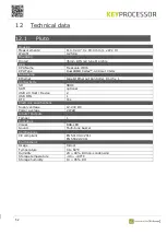
Page 52: ...it Ethernet Controller RJ 45 x 1 Connectivity SD SDHC SAM optional USB 2 0 Host Device 2 USB OTG 1 RTC Yes Electronic specifications Supply voltage 12 24V DC Power average 2 Watt Inputs Outputs Tamper 1 Indicators Visual RGB LED Sound Multi tone buzzer Certifications CE compliant EN 50130 4 2011 EN 55022 2011 Environment Usage Indoor Temperature 0 to 60 C Humidity 20 90 RH non condensing Storage t...

Page 53: ... 0 24V DC Power Average 0 48W no load Digital I O Tamper Switching to GND Digital output O1 O2 O3 O4 O5 O6 Max Voltage 28V Open collector output sink current Max current 300mA Polyfuse High power output H1 H2 Switching to GND max 2 5A Digital input T1 T2 Switching to GND 20K ohm Digital input D0 D1 Reader IO 1 Switching to GND 20K ohm Digital input D0 D1 Reader IO 2 Switching to GND 20K ohm Monito...

Page 54: ...0 85 C 10 95 RH Polyfuse Type PTC Fuse Case style Thermal derating At 10 C the hold current will increase to 130 At 25 C no derating At 60 C the hold current will reduced to 60 Certifications CE compliant EN 55022 2010 EN 50130 4 2011 ...

Page 55: ...lectromagnetic compatibility The product of the declaration described above is in conformity with the requirements of the following specifications Date 2 November 2017 Dr W B J M Janssen CTO Keyprocessor B V Paasheuvelweg 20 1105 BJ Amsterdam The Netherlands Documents No EN 55022 2011 European limits and methods of measurement of radio disturbance characteristics of information technology equipmen...

Page 56: ...netic compatibility The product of the declaration described above is in conformity with the requirements of the following specifications Date 2 November 2017 Dr W B J M Janssen CTO Keyprocessor B V Paasheuvelweg 20 1105 BJ Amsterdam The Netherlands Documents No EN 55022 2010 European limits and methods of measurement of radio disturbance characteristics of information technology equipment EN 5013...

Page 57: ...57 14 Technical drawings 14 1 72000310 Pluto Orion setup with network connection and power supply ...

Page 58: ...58 14 2 72000206 Pluto Orion with Sirius RS485 and IO ...

Page 59: ...59 14 3 72000202 Pluto Orion with Sirius clock data Wiegand and I O ...

Page 60: ...60 14 4 72000207 Pluto Orion with IO Sirius Clock data Wiegand and Orbits ...

Page 61: ...61 14 5 72000304 Pluto with power supply and USB RS232 converter ...

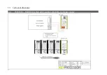
Page 62: ...62 14 6 72000203 Pluto Orion with kpBus ...

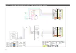
Page 63: ...63 14 7 72000204 Orion with kpSensor bus ...

Page 64: ...64 14 8 72000602 Pluto Orion stacked with 8x RS485 Sirius i readers ...

Page 65: ...65 14 9 72000602 Pluto Orion with clock data or Wiegand readers ...

Page 66: ...66 14 10 72000602 Pluto Orion with RS485 readers kpBus combi ...

Page 67: ...67 14 11 72000504 Polyx with kpBus ...

Reviews: