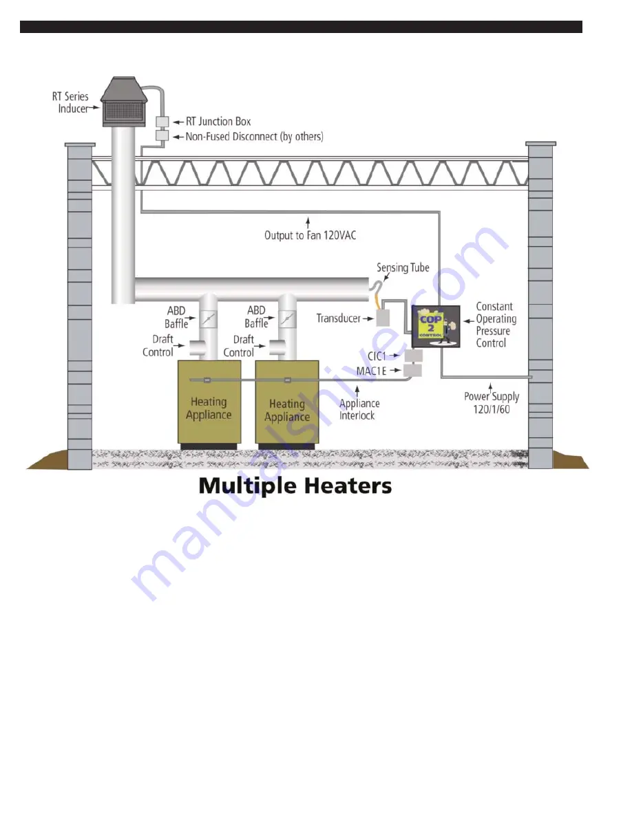
COP2 WITH MULTIPLE HEATERS - SAMPLE LAYOUT DIAGRAM
Page 1: ...or to the blue LED on the UC1 circuit board being illuminated Once the blue LED is lit pull the insulated connector from terminal P1 of the UC1 circuit board off and verify that 10 seconds later that...
Page 2: ...COP2 WITH MULTIPLE HEATERS SAMPLE LAYOUT DIAGRAM...