V-groove
Fig 5
your planer show signs of becoming dull, replace
them.
Caution:
Always use two hands on the tool for
any operation, this assures you maintain control
and avoid the risk of serious personal injury.
Workpiece must always be properly supported
and clamped so both hands will be free to control
the planer.
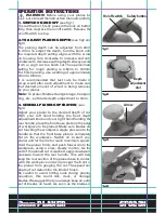
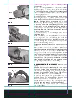
4. CHAMFERING
(see fig5 and fig6)
The planer has been designed with chamfering
grooves in the front base plate. The purpose for
this groove is chamfering edges of boards.
Before making a cut on good timber, practice
cutting on scrap timber to determine the amount
to be removed. Clamp the work piece so it will
not move during this operation. Firmly holding
the cut depth adjustment knob with your left
hand and the rear handle with your right hand,
place the chamfering groove on the surface to be
cut. Start your planer and let it reach full speed,
then slowly move it into the work piece. Maintain
downward pressure to keep your planer flat at
the beginning and the end of the work surface.
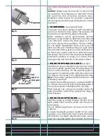
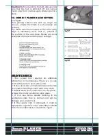
5. USING THE PARALLEL GUIDE
(see fig7)
Insert the screw provided through the hole on the
support of parallel guide. Then turn the screw into
the nut on the housing. Fix the parallel guide on
the support of parallel guide with the screw and
nut. Ensure the screws are tightened securely.
Note:
The parallel guide should be fitted on left
of housing (see fig7).
To adjust the parallel guide to required width of
cut, loosen the nut and slide the parallel guide to
the required position. Retighten the nut fully.
When making cuts using your parallel guide, the
guide should be held firmly against the edge of
the workpiece.
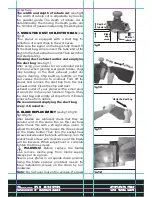
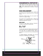
6. USING THE DEPTH GUIDE
(see fig8)
Insert the screw provided through the slot on the
depth guide. Then turn the screw into the nut on
the housing.
The cut depth adjustment can be set from 0mm
to 18mm.
To adjust the depth guide to depth of cut, place
the planer on a flat board, then loosen the screw
and slide the cut depth adjustment guide up and
down for required depth, then tighten the thumb
Fig 6
Screw
Parallel guide
Support of
parallel guide
Fig 7
Screw
Depth guide
Fig 8

