background image

Performance Series 450e 

9

GB


Spraying Technique

1

2

4

5

3

4.4   Taking the unit into operation with coating 

material

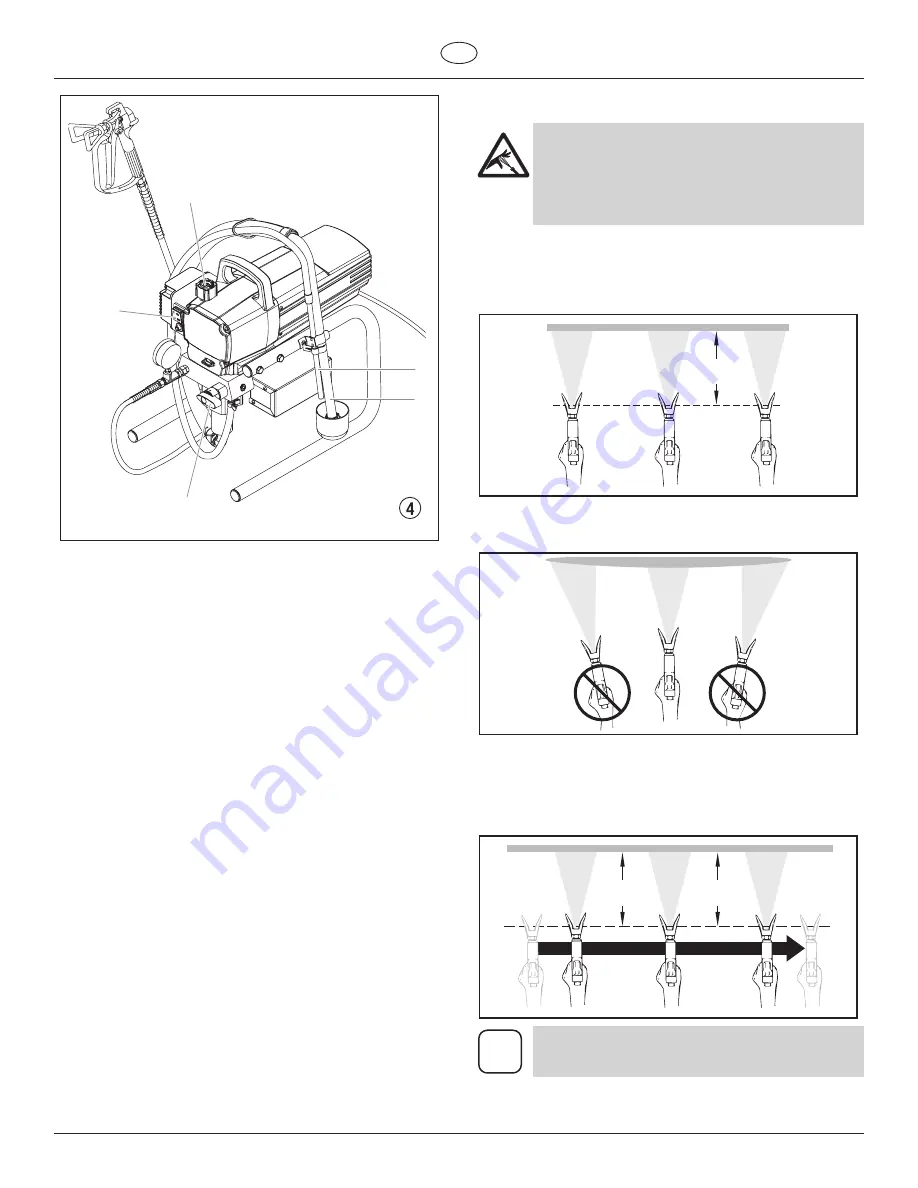
  1.  Immerse the suction tube (Fig. 4, Item 2) and return hose 

(1) into the coating material container.

  2.  Turn the pressure control knob counterclockwise (3) to 

minimum pressure.

  3.  Open the relief valve (4), valve position PRIME 


  (

k

 circulation).

  4.  Switch the unit (5) ON.

  5.  Wait until the coating material exudes from the return 

hose.

  6.  Close the relief valve, valve position SPRAY (

p

 spray).

  7.  Trigger the spray gun several times and spray into a 

collecting container until the coating material exits the 

spray gun without interruption.

  8.  Increase the pressure by slowly turning up the pressure 

control knob.


  Check the spray pattern and increase the pressure until 

the atomization is correct.


  Always turn the pressure control knob to the lowest setting 

with good atomization.

  9.  The unit is ready to spray.

5. 

Spraying technique

Injection hazard.  Do not spray without the tip 

guard in place.  NeVeR trigger the gun unless 

the tip is completely turned to either the spray 

or the unclog position.  ALWAyS engage the 

gun trigger lock before removing, replacing or 

cleaning tip.

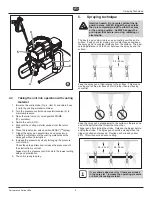
The key to a good paint job is an even coating over the entire 

surface.  Keep your arm moving at a constant speed and keep 

the spray gun at a constant distance from the surface.  The best 

spraying distance is 25 to 30 cm between the spray tip and the 

surface.  

25 - 30 cm

Keep the spray gun at right angles to the surface.  This means 

moving your entire arm back and forth rather than just flexing 

your wrist.

Keep the spray gun perpendicular to the surface, otherwise one 

end of the pattern will be thicker than the other.

Trigger gun after starting the stroke.  Release the trigger before 

ending the stroke.  The spray gun should be moving when the 

trigger is pulled and released.  Overlap each stroke by about 

30%.  This will ensure an even coating.

25 - 30 cm

25 - 30 cm

i

If very sharp edges result or if there are streaks 

in the spray jet – increase the operating pressure 

or dilute the coating material.

Summary of Contents for 558073

Page 1: ...Edition 9 2010 0558 940D Performance Series 450e GB Operating manual Performance Series 450e Airless high pressure spraying unit Models 0558067 0558073...

Page 2: ...must not be used Secure Titan spray gun using the safety catch on the trigger 3 Ensure that the unit is properly earthed The connection must take place through a correctly earthed two pole and earth s...

Page 3: ...hose 10 7 Interruption of work 10 8 Cleaning the unit shutting down 10 8 1 Cleaning unit from outside 10 8 2 Suction filter 11 8 3 Cleaning the high pressure filter 11 8 4 Cleaning Airless spray gun...

Page 4: ...st be rated at or above the maximum operating pressure range of the sprayer This includes spray tips guns extensions and hose NOTE TO PHYSICIAN Injection into the skin is a traumatic injury It is impo...

Page 5: ...d or come in contact with body Vapors can cause severe nausea fainting or poisoning PREVENTION Use a respirator or mask if vapors can be inhaled Read all instructions supplied with the mask to be sure...

Page 6: ...appropriate cleaning materials Coating materials with sharp edged additional materials These have a strong wear and tear effect on valves high pressure hose spray gun and tip The durability of these p...

Page 7: ...hose 3 Return hose 4 Suction hose 5 Frame 6 Drip cup 7 Power cord 8 Relief valve Lever position vertical PRIME k circulation Lever position horizontal SPRAY p 9 Pressure control knob 10 ON OFF switch...

Page 8: ...spray gun 5 with the selected tip onto the high pressure hose 4 Tighten the union nuts at the high pressure hoses firmly so that coating material does not leak 5 1 4 2 3 5 Fill the oil cup with Pisto...

Page 9: ...ction hazard Do not spray without the tip guard in place NEVER trigger the gun unless the tip is completely turned to either the spray or the unclog position ALWAYS engage the gun trigger lock before...

Page 10: ...ring operation without problems After you have finished spraying clean the unit Under no circumstances may any remaining coating material dry and harden in the unit The cleaning agent used for cleanin...

Page 11: ...eplace the filter cartridge 7 Check the O ring 4 replace it if necessary 8 Push the new or cleaned filter into the pump manifold 9 Screw in filter housing 1 and tighten it as far as possible with the...

Page 12: ...ating material flows through the return hose when the relief valve is in the SPRAY p spray position 6 Packings sticky or worn 7 Valve balls worn 8 Valve seats worn Measures for eliminating the malfunc...

Page 13: ...rayed 2 Pressure setting incorrect 3 Volume too low 4 Coating material viscosity too high 1 Pressure setting too low Measures for eliminating the malfunction 1 Remove and replace packing 2 Remove and...

Page 14: ...r and then remove the front cover 2 Switch the unit ON and then OFF so that the piston rod is positioned in the lower stroke position Danger of crushing do not reach with the fingers or tool between t...

Page 15: ...retainer nut 6 from the pump manifold 2 and remove piston guide 7 7 Remove upper packing 8 and lower packing 9 from the pump manifold 2 5 6 7 8 2 4 1 9 3 10 8 Clean pump manifold 2 9 Lubricate upper p...

Page 16: ...of this manual 6 Using the four heat sink assembly screws 3 install the heat sink assembly 4 onto the gear box housing 5 Tighten the screws securely 7 Disconnect the black and red wires coming from th...

Page 17: ...ing reassembly make sure the thrust washer 9 is in place i Refill the gear box in the pump housing with five ounces of Lubriplate GR132 P N 0293396 1 2 3 4 6 7 8 9 5 11 7 Replacing the Transducer 1 Op...

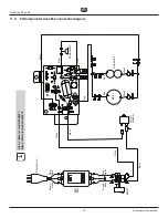
Page 18: ...FB M F M F M F F F F F F 1 2 3 4 M F F WH6 WH1 WH2 WH7 WH4 WH5 Red Red Blue Blue Brown black Blue white Brown black Blue white Motor EMI filter Microswitch Power cord Switch Capacitors Black Black Whi...

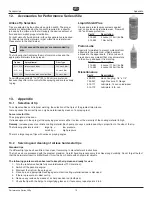
Page 19: ...Part Description 490 012 Hose Coupling 1 4 x 1 4 730 397 High Pressure Fl Gauge 314 171 Lubriplate 14 ounce individual 314 172 Lubriplate 6 lb can 13 Appendix 13 1 Selection of tip To achieve faultles...

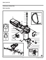
Page 20: ...nce Series 450e 30 29 1 2 20 21 24 23 22 25 26 27 28 13 14 15 16 17 18 19 6 3 4 10 11 12 5 8 3 32 34 35 36 38 37 33 31 4 9 7 Main Assembly 0558 466 110V 20 Ft 800 741 120V 8 25 Ft BS4343 NEMA 5 15P 58...

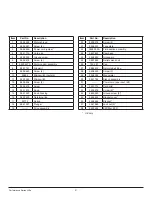
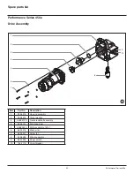
Page 21: ...housing 16 9822 522 Retaining ring 17 02712 Spring 18 0551 521 Plunger 19 Drive assembly Item Part No Description 20 0509 218 Screw 4 21 0558 301 Face plate 22 0558 263A Fluid section assembly 23 050...

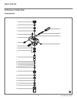
Page 22: ...22 Performance Series 450e Spare parts list Performance Series 450e 24 25 26 27 1 2 3 4 5 7 6 8 11 9 12 14 13 15 16 17 18 19 20 21 22 23 10 Fluid section...

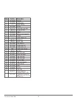
Page 23: ...r cage 13 0551 263 Crush washer 14 0516 303 Outlet valve ball 15 0551 620 Outlet valve seat 16 13481 Outlet valve retainer 17 704 535 Bushing 18 0509 581 Inlet valve seal 19 0509 591 Lower ball guide...

Page 24: ...sembly Item Part No Description 1 0558 316 Housing assembly 2 0508 573 Thrust washer 3 0508 572A Gear crankshaft assembly 4 0509 121 2nd stage gear 5 0558 353A Motor assembly 120V 6 9820 213 Washer 4...

Page 25: ...Performance Series 450e 1 2 3 7 6 4 5 Motor Assembly Item Part No Description 1 0522 100 Capacitor assembly 2 806 304 Fan shroud 2 3 704 322 Screw 2 4 806 308 Fan 5 9804 916 Screw 6 0551 543 Tie wrap...

Page 26: ...escription 1 0508 377 Cord holder 2 806 071 Leg left 3 9885 546 Plug 2 4 0551 527 Screw 5 0509 856 Nut 6 0290 234 Leg right 7 806 216 Tube clip 8 0551 434 Screw 9 0508 381 Drip cup 10 9805 230 Screw 1...

Page 27: ...27 1 3 2 4 Spare parts list Performance Series 450e Suction system Item Part No Description 1 0551 706 Siphon hose 2 9850 638 Tie wrap 2 3 0551 707 Retun tube 4 0279 459 Clip 0551 705 Siphon tube asse...

Page 28: ...RCHANTABILITY AND FITNESS FOR A PARTICULAR PURPOSE TO THE EXTENT PERMITTED BY LAW THE DURATION OF ANY IMPLIED WARRANTIES WHICH CANNOT BE DISCLAIMED IS LIMITED TO THE TIME PERIOD SPECIFIED IN THE EXPRE...

Reviews: