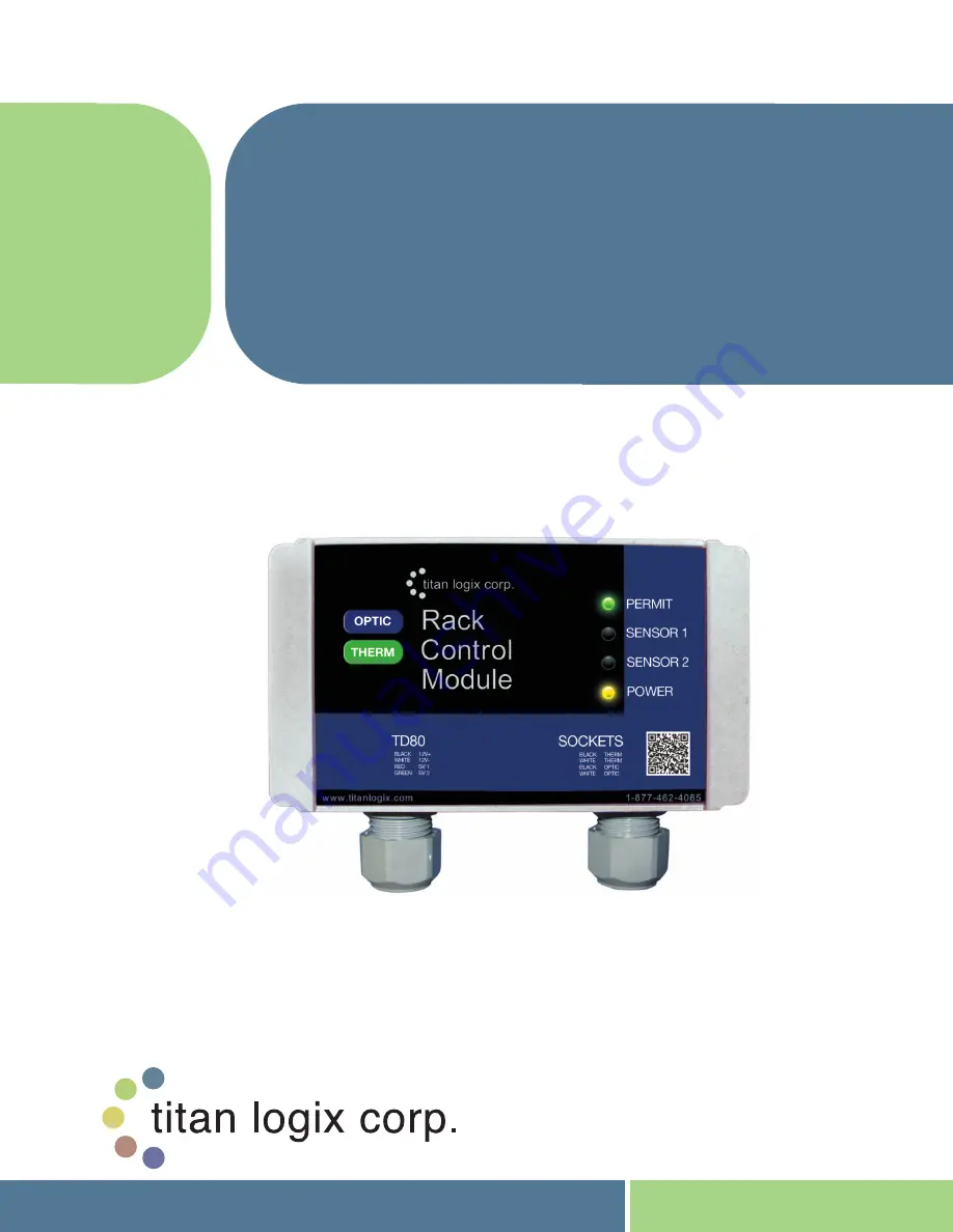
RACK CONTROL
MODULE
™
INTERFACE DEVICE
FOR CONNECTING
TD80
TM
GAUGING SYSTEMS TO THERMISTOR
AND OPTIC STYLE LOADING RACKS
*Also available in an optic-only model
PRODUCT MANUAL
TPM
007
Revision
1.
2
Page 1: ...RACK CONTROL MODULE INTERFACE DEVICE FOR CONNECTING TD80TM GAUGING SYSTEMS TO THERMISTOR AND OPTIC STYLE LOADING RACKS Also available in an optic only model PRODUCT MANUAL TPM 007 Revision 1 2 ...
Page 2: ...sportation or other expenses will be recognized In the event of an accepted warranty claim TLC shall assume financial responsibility only to the extent of TLC s invoiced price of the particular product Warranty does not cover the removal reinstallation or modification of equipment All repairs are FOB Edmonton Alberta and or Lampman Saskatchewan and or Overland Park Kansas Should repair be required...
Page 3: ...r Installation 8 Figure 2 1 Rack Control Module 9 Figure 3 1 Wiring For Standard API Optic and Thermistor Sockets 14 Figure 3 2 Wiring For Standalone J560 7 Pin Optic Socket 15 Figure 3 3 Wiring For Optic API Socket and RCM J560 Optic Socket 16 Figure 3 4 Wiring For Standard API Optic and Thermistor Sockets and RCM J560 Optic Socket 17 Figure 3 5 TD80 and RCM Interconnection no Junction Box Single...
Page 4: ...auging and Overfill Prevention System details THIS MANUAL INCLUDES Introduction Description of the key features and components of the Rack Control Module Operation Description of Operation and Alarms Installation Description of mounting and wiring of equipment Troubleshooting Description of possible problems their probable causes and solutions Technical Reference Technical Specification Disclaimer...
Page 5: ...interface It provides the benefit of both optic and thermistor terminal rack controller interfaces along with enhanced features to provide maximum safety while loading hazardous products About the TD80 System 1 3 2 The TD80 Level Transmitter is the heart of the TD80 level measurement system The TD80 transmitter uses Guided Wave RADAR GWR to measure liquid level in a tank It does not use any moving...
Page 6: ...l prevention Optional Components 1 3 4 Rack Control Module The RCM is an accessory that enables secondary overfill prevention when used with industry standard optic and thermistor terminal rack controllers The TD80 transmitter sends loaded volume alarm states and detected errors by the SV Bus to the RCM Finch display and optional MIC 10 The RCM continuously tests the validity of this information m...
Page 7: ... set from 3 and lower The TD80 transmitter is the source of this alarm The HH alarm is activated by a measured volume equal to or exceeding the alarm level set during programming Spill Alarm Spill is an approaching overfill condition Dual Rod TD80 transmitters and probes are factory set at 7 5 below the tank top while Coaxial TD80 transmitters and probes are selectable in the range of 2 5 down to ...
Page 8: ...Rack Control Module TM Product Manual Rev 1 2 May 9 2014 Page 7 TPM 007 Graphical Glossary of Terms 1 4 Dual Rod Probe Truck and Trailer Installation Figure 1 1 Dual Rod Probe Truck Trailer Installation ...
Page 9: ...Rack Control Module TM Product Manual Rev 1 2 May 9 2014 Page 8 TPM 007 Coaxial Probe Truck and Trailer Installation Figure 1 2 Coaxial Probe Truck Trailer Installation ...
Page 10: ... Solid Green The RCM is providing a signal to the terminal rack controller to permit loading Sensor 1 Indicates alarm state of the TD80 transmitter monitoring compartment 1 Solid Red Active overfill spill or system error alarm from compartment 1 Loading is denied until the indicator is OFF OFF No alarms are detected for compartment 1 Sensor 2 Indicates alarm state of the TD80 transmitter monitorin...
Page 11: ...moved and then reapplied This allows the operator to resolve the problem before loading continues Sequence of Events 2 2 Event Sequence Inputs are Battery Power and TD80 Data Permissive Signal to the Terminal Rack Controller OFF is Loading Denied ON is Permitted Power Indicator Sensor 1 Indicator Sensor 2 Indicator Permit Indicator Normal Operating Conditions 1 Power off OFF OFF OFF OFF OFF 2 Powe...
Page 12: ...d Red 12 Power on unload to 2 LO empty tank for more than 1 minute ON Solid Yellow OFF OFF Solid Green Normal System Configuration Conditions 13 TD80 Offset Calibration OFF until next power cycle Solid Yellow Solid Red Solid Red Solid Red 14 TD80 transmitter programming using Birdfeeder OFF then ON when normal level communication resumes Solid Yellow OFF OFF Solid Red Error and Failure Conditions ...
Page 13: ...ate and local codes b Fuses and components appropriate for the area classification 2 The tank is completely drained of liquid and vapour free 3 No drilling or welding to the tank and frame without first consulting with the tank manufacturer Installation Steps 3 3 Checked Step 1 Program the TD80 2 Install the 1 NPT Top Fitting 3 Install the Anchor Cone 4 Install the Probe 5 Mount the Transmitter 6 ...
Page 14: ...ure or junction box to prevent premature failure due to corrosion 5 Secure all wires and cabling with clips or cable ties 6 Tighten all compression fittings 7 Refer to the specific installation wiring diagrams and instructions for details See the figures below for sample electrical wiring installation Single compartment installations have both Sensor 1 and 2 RCM wiring connected to the single SV B...
Page 15: ...Rack Control Module TM Product Manual Rev 1 2 May 9 2014 Page 14 TPM 007 Figure 3 1 Wiring For Standard API Optic and Thermistor Sockets ...
Page 16: ...Rack Control Module TM Product Manual Rev 1 2 May 9 2014 Page 15 TPM 007 Figure 3 2 Wiring For Standalone J560 7 Pin Optic Socket ...
Page 17: ...Rack Control Module TM Product Manual Rev 1 2 May 9 2014 Page 16 TPM 007 Figure 3 3 Wiring For Optic API Socket and RCM J560 Optic Socket ...
Page 18: ...Rack Control Module TM Product Manual Rev 1 2 May 9 2014 Page 17 TPM 007 Figure 3 4 Wiring For Standard API Optic and Thermistor Sockets and RCM J560 Optic Socket ...
Page 19: ...Rack Control Module TM Product Manual Rev 1 2 May 9 2014 Page 18 TPM 007 Figure 3 5 TD80 and RCM Interconnection no Junction Box Single Installations Wiring Schematic ...
Page 20: ...Rack Control Module TM Product Manual Rev 1 2 May 9 2014 Page 19 TPM 007 Figure 3 6 TD80 and RCM Interconnection no Junction Box Single Installations Wiring Diagram ...
Page 21: ...Rack Control Module TM Product Manual Rev 1 2 May 9 2014 Page 20 TPM 007 Figure 3 7 TD80 and RCM Interconnection Single Installation Wiring Schematic ...
Page 22: ...Rack Control Module TM Product Manual Rev 1 2 May 9 2014 Page 21 TPM 007 Figure 3 8 TD80 and RCM Interconnection Single Installation Wiring Diagram ...
Page 23: ...Rack Control Module TM Product Manual Rev 1 2 May 9 2014 Page 22 TPM 007 Figure 3 9 TD80 and RCM Interconnection Dual Installation 2x Single Displays Wiring Schematic ...
Page 24: ...Rack Control Module TM Product Manual Rev 1 2 May 9 2014 Page 23 TPM 007 Figure 3 10 TD80 and RCM Interconnection Dual Installation 2x Single Displays Wiring Diagram ...
Page 25: ...e Volume display alarm response and RCM indicators are tested from 2LO to Spill and back to 2LO 7 Test the optional 4 20mA output 8 Test the Optic and or Thermistor sockets Table 3 2 System Test and Verification Checklist 1 Turn power on to the TD80 system The Display should turn on and go through its start up sequence approximately 10 seconds long a Finch Display is tested showing numbers 0 thru ...
Page 26: ... alarms a Ensure RCM Indicators are as follows i Power Indicator is ON and solid YELLOW ii Sensor 1 and 2 are OFF iii Permit is ON and solid GREEN 1 If the Permit is SOLID RED turn the power OFF and then back ON 6 Confirm that the following occurs when the probe is shorted by a hand or metal tool to simulate liquid level at selected points a 2 LO is displayed when the tank level is less than 5 5 V...
Page 27: ...ELLOW 2 Comp 1 or 2 is solid RED for the compartment being tested 3 Permit is ON and solid RED i Spill and HH alarms deactivate when the tank level decreases more than 2 below the HH alarm setting i Display returns to normal not flashing SPill ii Installed light and horn deactivate iii Installed onboard overfill prevention system deactivates iv RCM Indicators are as follows 1 Power Indicator is ON...
Page 28: ...Socket ii Confirm that the Good Indicator is ON solid iii Place a hand or metal tool across the probe and slide up the probe to the HH alarm level iv Confirm that the Finch display indicates a HH alarm and the UTT indicates Fail ON solid v Slide the hand or metal tool down to the bottom of the probe and confirm that the UTT indicates Good solid after 1 minute or cycling the power d Configure the U...
Page 29: ...ing details confirm that the TD80 transmitter is programmed for the compartment it is installed on and reprogram if necessary Offset calibration will halt if the adjusted level causes the High High alarm setting to exceed the Spill alarm level The High High alarm is programmed to be no closer than below the Spill alarm This is also an indication of incorrect programming to be resolved The adjusted...
Page 30: ...number of inches and fractional part of an inch to adjust the TD80 reported volume e At the next site load the tank to approximately 3 4 full Note the TD80 reported volume i For example 168 1 bbl is loaded for the calibration as shown on the Finch Display f Refer to the manufacturer s depth chart Determine the depth at the currently loaded volume reported by the TD80 i According to the sample dept...
Page 31: ... off c Press and hold either the Up or Down button while turning on gauge power d Continue to hold the button down until CAL is displayed and then release it e After the normal display start up sequence CAL will be displayed flashing for several seconds and then the current volume measured by the TD80 This should be close to the actual volume f Use the Up and or Down buttons to adjust the displaye...
Page 32: ...cal circuit The tip is usually pointed and sharp enough to pierce the insulation of a wire for circuit testing Most test lights have a low resistance path due to the cold resistance of the light bulb This makes it useful to apply either power or ground to a part of the circuit Short circuit current is limited by the light bulb to several hundred milliamps in a typical automotive circuit Care must ...
Page 33: ...circuit b Clip on battery power probe each component at the shorted terminal and disconnected wire A short circuit to ground is indicated by the light partially or fully illuminating 2 Short Circuit to power isolation a Disconnect the shorted wire at each component to isolate the short circuit b Clip on ground probe each component at the shorted terminal and disconnected wire A short circuit to po...
Page 34: ...timeter Do not use a battery charger for testing The following troubleshooting steps are organized by system or circuit function and symptoms These are some of the most common system wiring and component failures along with suggested troubleshooting and repair steps As an alternative please also refer to the pictorial Rack Control Module Operator Guide for loading unloading alarm and error conditi...
Page 35: ...for a loose or disconnected wiring inside the junction box Repair or replace the wiring For Single or Dual TD80 Systems Permit RED Sensor 1 OFF Sensor 2 OFF Power BLINKING YELLOW WHAT TO DO DETAILS WHAT TO CHECK REMEDY Measure the battery voltage inside the RCM junction box Place the DMM probes on the power and ground terminals i Voltage measures greater than 8VDC Typical vehicle battery voltage i...
Page 36: ...r Dual TD80 Systems Permit GREEN Sensor 1 OFF Sensor 2 OFF Power SOLID YELLOW WHAT TO DO DETAILS WHAT TO CHECK REMEDY Use the UTT to test the permissive signal at the API socket s a If the UTT indicates GOOD i Check for worn or corroded pins on the API socket s Repair or replace the socket ii Problem with the terminal rack controller cable Inform terminal rack operator of problem b If the UTT indi...
Page 37: ...oken wiring at the RCM junction box Repair or replace the wiring 2 Check the wiring between the junction box and RCM Repair the wiring or replace the RCM For Single or Dual TD80 Systems Permit DIM RED BLINKING Sensor 1 DIM RED BLINKING Sensor 2 DIM RED BLINKING Power DIM RED BLINKING WHAT TO DO DETAILS WHAT TO CHECK REMEDY Check for incorrect wiring of SV input and power input One or Two SV channe...
Page 38: ...RCM junction box Repair or replace the wiring 2 Check the wiring between the junction box and RCM Repair the wiring or replace the RCM For Single or Dual TD80 Systems Permit RED Sensor 1 RED Sensor 2 RED Power SOLID YELLOW WHAT TO DO DETAILS WHAT TO CHECK REMEDY Check the Finch display for an active alarm system error code or loss of communication Clear the alarm or resolve the TD80 system malfunc...
Page 39: ...r 2 OFF Power SOLID YELLOW WHAT TO DO DETAILS REMEDY If both optic and thermistor sockets continue to permit a Check the sockets for shorted terminals and wires b Check the wiring between the RCM and the sockets Repair or replace the wiring If only one socket continues to permit a Check the socket s for loose or shorted wiring b Replace the affected optic or thermistor terminator module c Check th...
Page 40: ...lume of product loaded at the terminal rack i If the volume loaded is less than the expected HH alarm level Confirm the HH alarm level by checking the highest allowable fill alarm setting This is the HH alarm volume a If HH alarm volume is too low have the TD80 transmitter reprogrammed with the correct HH alarm setting b If the HH alarm volume is correct perform an Offset Calibration to restore th...
Page 41: ...ions a Does the problem always appear in the same way or does it change from time to time 3 Consider the history a Was the system recently installed repaired or modified b Does this problem have a history of reappearing after repair 4 Try to reproduce the problem a Does the problem appear when the system is first turned on or after some period of time b Does the problem seem to be vibration relate...
Page 42: ...0 transmitter is being interrupted a Check all electrical wiring and connections between the affected transmitter and display ii Finch is operating normally showing volume 1 Check the SV Bus data wiring of the affected Sensor channel between the RCM and the Finch or junction box terminated wiring d Permit light goes from green to red and then back to green after about 10 seconds Sensor 1 and or Se...
Page 43: ...Optical Booster Optic only model does not include thermistor socket with dummy Installation Manual Quick Reference Operator Guide Specifications 5 2 Power 8 30 VDC Current Consumption 40mA at 12V Ambient Temperature Range 40C to 40C Communications TD80 SVBus Environment Hazardous area approvals Class I Div 2 Groups C D T3 Intrinsically safe associative Weatherproof NEMA 4 or Type 4 Dimensions Figu...
Page 44: ...wan Canada S0C 1N0 P 306 487 2883 F 306 487 2889 Toll Free 1 877 462 4085 TSX V TLA Sales Department Email us at sales titanlogix com Service Department Email us at service titanlogix com Find us online at www titanlogix com Kansas Branch 8900 Nieman Road Overland Park Kansas USA 66214 P 913 541 8200 F 913 541 8203 Manufactured by Manufactured in Canada ...