background image


32


Continued Table 7


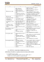
8. Free access 
in one direction 
and locked 
access in 
opposite 
direction 

"FREE"  button  to  be 
pushed  for  access  in 
chosen direction («A» or 
«B») 

and 

"LOCK" 

button  to  be  pushed  to 
lock  access  in  opposite 
direction 

Green  arrow  of  authorized 
free  access  in  chosen 
direction  is  lit  and  red 
LED  display  of  locked 
access direction is lit 

Glass 

leaves 

are 

pushed  inside    the  
turnstile 

opening  

access 

  in 

  the 

intended  direction  

9. Locked 
access in one 
direction 

"LOCK"  button  to  be 
pushed  to  lock  access  in 
chosen  direction ("A" or 
"B")* 

Red LED of locked access 
in  one  chosen  direction  is 
lit  

Make sure that  glass  
leaves are locked and  
they can't be pushed  
inside the turnstile 

10. Locked 
access in both 
directions 
 

Both "LOCK" buttons to 
be pushed to lock access 
in  both  directions  ("A" 
and "B")** 

Red LED of locked access 
in both directions is lit 

Make  sure  that  glass  
leaves  are locked and  
they  can't  be  pushed  
inside the turnstile 

11. Activation 
of "panic" 
mode 

"PANIC" button to be  
pushed and hold within 
at least 7 sec.** 


Green arrows of 
authorized free access in 
both directions are lit 

Swing panels are 
opened in different 
directions 

12 Deactivation 
of antipanic 
device 

"PANIC" button to be 
pushed 

Blue LED brightness is 
changed.  
Glass partition blue 
backlight is lit 

Make sure that the 
glass doors are locked 
and cannot be pushed 
inside the turnstile 

*

 In this case other control desk buttons of single and free access in chosen direction are locked. 

**  In this case all control desk buttons of single and free access in both directions are locked


2.3.2.2  After  all  checks  are  completed  and  satisfactory  results  are  achieved,  the  turnstile  is 

ready for long-term operation. 

2.4 Contingency actions  

For emergency human escape (in case of fire, acts of God etc.) and enabling free access the 

turnstile  to  be  unlocked  from  control  desk  by  issuing  the  relevant  command.  For  full  opening  of 
access way the "PANIC" function to be used or "PANIC" button on control desk to be pushed and 
held for more than 7 seconds or a signal is sent to the relevant input (in3) of the turnstile controller. 
In  case  of  mains  power  failure  the  turnstile  automatically  switches  to  power  supply  from  backup 
battery (optional).  

If the mains  power is  not  recovered and battery is discharged, the  glass  blades  are  fully  put 

manually to the turnstile cabinet slots to make access way free. 


Summary of Contents for JETPAN

Page 1: ...1 TiSO PRODUCTION LTD WAIST HIGH TURNSTILE JETPAN OPERATION MANUAL AUIA 168 OM rev 1 2018 ...

Page 2: ...4 4 2 Possible malfunctions 34 4 3 JETPAN 1 turnstile blade initialization procedure 35 4 4 Postrepair checkout 37 5 TRANSPORTATION AND STORAGE 37 5 1 Turnstile storage 37 5 2 Turnstile transportation 38 6 DISPOSAL 38 7 MANUFACTURER S WARRANTY AND TERMS OF WARRANTY MEAINTENANCE 38 Annex А Overall and installation dimensions of the JETPAN 1 type turnstile 40 Annex B Control desk and connection diag...

Page 3: ... and conditions of transportation storage installation and operation So fulfillment of all requirements specified in this document is mandatory The turnstile JETPAN can be installed either singly or in line The single turnstile includes two cabinets left hand and right hand each of which has one glass blade The turnstile row is provided by installation one more or a number of additional cabinets e...

Page 4: ... JETPAN 1 consisting of Master and Slave pedestrian gates made of brushed stainless steel The turnstile T3 КСD SK ТU U 28 9 32421280 005 2018 Example of reference designation of the double turnstile JETPAN 2 consisting of one consisting of servo operated Master Slave pedestrian gate made of polished stainless steel The turnstile T3 КСD РK X ТU U 28 9 32421280 005 2018 Due to regular improvement of...

Page 5: ...should be connected to AC network with parameters specified in p 1 2 Specifications inspection adjustment and repair should be performed only after the turnstile is deenergized After the turnstile is purchased it should be unpacked and its integrity should be checked In case of doubt in integrity of the turnstile it should not be used and the customer shall refer to the supplier or to the manufact...

Page 6: ...he turnstile correspond to the values specified in Table 1 Dimensions of turnstile group Table 1 Designation of turnstile modification type Access way width Dimensions mm Max weight kg H L B Т3 КСD XK_ 500 500 500 1522 1800 HG 1080 1000 1006 211 Т3 КСD XK_ 500 500 500 500 1870 345 When the turnstile with more than two access ways is ordered Ltotal 790 s b where s number of 500 mm access ways stаnd...

Page 7: ...XK X 134 Overall dimension for the turnstile with glass countertop Fig 3 Overall dimensions of the turnstile cabinet 1 1 4 The operation condition parameters according to GOST 15150 69 are specified in Table 3 Table 3 Operation conditions For climatic modification Parameter value 1 2 3 Ambient air temperature NF4 1 С to 40 С Relative air humidity 80 at 20ºС Ambient air allowable pressure 84 to 106...

Page 8: ...e at least 1 500 000 accesses mean service life between overhauls at least 10 years 1 2 Specifications Key parameters of the turnstile are specified in Table 4 Table 4 Parameter description Unit measure Parameter value Traffic flow capacity in free access mode at least man min 30 Opening closing time s 0 8 Maximum access way width mm 500 Power supply voltage AC power supply primary V Hz 100 240 50...

Page 9: ...er Slave with one each of which has two glass leaf reference designation Т3 КСD ХK Х 1 3 2 Design of the single JETPAN 1 type turnstile 1 2 8 3 5 6 7 4 10 9 1 location for card reader 2 LED display 3 IR access sensors 4 Glass panel leaf 5 Jumper Fixed glass 6 Lid or glass countertop 7 End panel 8 Base 9 Side panel front and rear 10 Turnstile operating mechanism Fig 4 Design of the single turnstile...

Page 10: ...he single turnstile control desk equipped with power supply unit circuit breaker and battery is installed only in the cabinet Master from the protected area side 1 3 3 Design of the JETPAN 2 type turnstile See Fig 5 The turnstile is an additional cabinet JETPAN 2 Master Slave with two leaves glass panels The number of additional cabinets is specified in order The turnstile JETPAN 2 operates only a...

Page 11: ...s 4 Glass panel leaf 5 Jumper Fixed glass 6 Lid or glass countertop 7 End panel 8 Base 9 Side panel front and rear 10 Turnstile operating mechanism Fig 5 Design of the turnstile JETPAN 2 Т3 КСD ХK X 1 3 4 Design overall and installation dimensions of the turnstile are shown in Annex A ...

Page 12: ... there is no any obstacle in the leaves movement area 1 4 1 3 Seven infrared sensors 3 installed on side panels of the turnstile from access side are designed for detection of the turnstile access preventing closing of leaves during pedestrian access in immediate proximity to them and minimizing personal injury during the turnstile access 1 4 1 4 Leaf 1 is made from 10 mm tempered glass and is loc...

Page 13: ...try and exit free entry and exit 1 4 2 General appearance of the turnstile operating mechanism and control desk Fig 7 General appearance of and design of operating mechanism and control desk of the turnstile JETPAN 1 Master cabinet Legend 1 pulley 2 magnetic sensor 3 crank 4 tensioning roller 5 tooth belt 6 drive 7 glassholder 8 bracket retainer 9 retractable glass 10 retractable device rack 11 te...

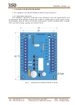
Page 14: ...or the turnstile installation multi purpose measurement instrumentation and installation tools are sufficient 1 6 Description and operation of controllers as integral component of the turnstile 1 6 1 Controller AUIA 206 21 20 00 1 6 1 1 Appearance of controller AUIA 206 21 20 00 is shown in Figure 8 1 6 1 2 Description of operation The controller provides algorithm of operation of the whole turnst...

Page 15: ...ess way analyzing 6 IR barriers As soon as pedestrian is behind the blades line they close the controller generates the signal DETECTION OF ACCESS of 0 3 second duration outputs OUT3 or OUT4 and LED display is switched from green to red After the pedestrian turnstile access the controller removes the signal ACCESS IS OCCUPIED and returns to INITIAL STATE FREE ACCESS The turnstile goes to this mode...

Page 16: ...e off and blades and light indication will be set according to the current mode The purpose of the controller contacts intended for connection to peripherals is specified in Table 5 1 ON when command is issued the turnstile will open for 5 seconds OFF when command is issued the turnstile will open for the time set in ACS 2 ON Outputs OUT1 5 will be NC OFF Outputs OUT1 5 will be NO 3 5 Not usable 6...

Page 17: ...rrier in the direction of movement and is removed after cancellation of the latter 1 type of output open collector 2 peak voltage on privacy key 55V 3 peak current of public key 100mA 4 resistance of public key 5 7 Ohm 5 active level of signal Factory setting logical 0 connection on GND ХТ3 3 OUT2 ACCESS B IS OCCUPIED EXIT ХТ3 4 OUT3 DETECTION OF ACCESS А EXIT Signal appears during barring of the ...

Page 18: ...rent of public key 250mA 4 resistance of public key 0 48 640 Ohm 5 active level of signal Factory setting logical 0 connection on GND ХТ1 2 B2 It is used for data transmission via serial port Interface RS 485 ХТ1 3 A2 Interface RS 485 ХТ2 1 12V power supply energization of controller 1 Power supply voltage 12V 2 Consumption current 150 mA ХТ2 2 12V ХТ2 3 GND common power supply common wire ХТ2 4 G...

Page 19: ...ller is designed to control DC motor intended to move the turnstile blades and electromagnetic brake installed on motor shaft Control is performed based on the signals coming from magnetic sensor as well as from motor current sensor Control commands come to inputs IN1 and IN2 from the controller AUIA 206 21 20 00 Fig 9 Appearance of controller РСВ 201 01 00 00 ...

Page 20: ... X1 11 GND X1 12 5 V EXIT Not applicable X2 1 GRN1 EXIT Not applicable X2 2 RED1 EXIT Not applicable X2 3 GRN2 EXIT Not applicable X2 4 RED2 EXIT Not applicable X2 5 MG1 EXIT Not applicable 1 type of output open collector 2 peak voltage on privacy key 50V 3 peak current of public key 5A X2 6 MG1 EXIT Not applicable X2 7 MG2 EXIT Not applicable X2 8 MG2 EXIT Not applicable X2 9 MOT1 EXIT Connection...

Page 21: ...e turnstile access in single access mode equals to 2 sec Escape door portal or pedestrian gate can be installed near the turnstile to increase the turnstile traffic flow capacity in case of emergency 2 2 Layout and installation 2 2 1 The turnstile and components of the scope of supply to be delivered to installation site in factory packing The turnstile to be unpacked only on installation site 2 2...

Page 22: ...on cord kit of end and pin wrenches kit of hexagons kit of screwdrivers hammer multimeter tester measuring tape marker pliers side cutters builder s level Fig 10 Tools and accessories for layout and installation ...

Page 23: ...ation of the JETPAN turnstile access ways Fig 11 The JETPAN turnstile access way arrangement options WARNING The damages occurred during the turnstile transportation are not covered by the manufacturer s warranty liabilities ...

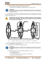
Page 24: ...stopped and the turnstile supplier to be referred to 3 Turnstile dismantling and relocation The turnstile cabinet to be removed from pallet See Figure 12 Top lid and interior lining side panel to be removed to provide access to the cabinet base fixation holes and terminal blocks For this purpose The turnstile lid to be removed by unscrewing screws on its butt ends from both sides Interior lining t...

Page 25: ...inked by control line optical sensor system requiring accurate cabinet positioning The cabinet relative position and vertical installation of the turnstile to be complied with Fig 13 Installation dimensions of the turnstile set JETPAN 1 and JETPAN 2 6 The relevant holes to be drilled on the surface according to the marking due to diameter of anchors 12 120М10 for the turnstile fixation 7 Anchor ja...

Page 26: ...26 Cables to be run in corrugated or metal pipes prior to pulling to prevent damages Fig 14 General view of connection between cabinets ...

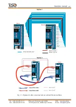
Page 27: ...1 5 mm 2 Wire 1 5 mm 2 Wire 0 22 0 5 mm RS B2 CUR AUX 2 AUX 3 IROUT 1 IROUT 3 IROUT 4 IROUT 6 IROUT 7 RS A2 AUX 1 IROUT 2 IROUT 5 IROUT 8 LED B R LED B G Option 2 Fig 15 Options of cable connection between cabinets Master and Slave ...

Page 28: ... the turnstile lid by unscrewing screws on butt ends See Fig 16 2 remove lining by by unscrewing screws on the turnstile frame 3 The turnstile to be installed upright at the prepared location Cables to be pulled through available service hole in the turnstile rack bottom end part by reclining the turnstile 4 align fixation holes at the turnstile bottom plate with the prepared surface holes accordi...

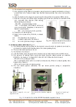
Page 29: ...s See Annex C d Proximity card readers to be installed if access control system ACS is available The turnstile doors and side panels Fig 17 to be installed on their fixation locations after the required mounting is completed Countertop to be fixed with screws 13 Installation of proximity card reader upon availability of access control system ACS See Fig 19 1 The turnstile top lid a and interior fi...

Page 30: ...he turnstile leaf swing area from foreign particles When mains cable of power supply unit is connected to the network the turnstile operating mechanism is energized leaves are locked from swinging in both directions barring access The turnstile is put in initial state Entry and Exit LED display is blue The turnstile performance to be checked at least 10 times in both directions upon generation of ...

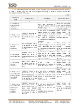
Page 31: ... one direction FREE button to be pushed for access in chosen direction A or B Green arrow of authorized free access in chosen direction is lit and blue LED display is lit in opposite direction Glass leaves are pushed inside the turnstile opening access in the intended direction 5 Free access in both directions Both FREE buttons to be pushed for access in both directions A and B Green arrows of aut...

Page 32: ...ions are lit Swing panels are opened in different directions 12 Deactivation of antipanic device PANIC button to be pushed Blue LED brightness is changed Glass partition blue backlight is lit Make sure that the glass doors are locked and cannot be pushed inside the turnstile In this case other control desk buttons of single and free access in chosen direction are locked In this case all control de...

Page 33: ...ICE LIFE OF WHICH HAS EXPIRED 3 2 2 When instrumentations are prepared for operation it is necessary to strictly comply with the safety requirements specified in the instrumentation instruction manuals 3 3 Maintenance procedure 3 3 1 The turnstile maintenance includes preventive measures which are taken according to the established frequency to maintain the turnstile in operational condition decre...

Page 34: ...rk and earthing cable condition verification of the turnstile performance during manual control in the modes specified in Table 7 or when identification cards are used verification of reliability of the turnstile screw joints and earthing connections 4 ROUTINE MAINTENANCE 4 1 General guidelines Minor malfunctions of the turnstile are listed in Table 9 and to be remedied by the customer More compli...

Page 35: ...aned from dust Infrared sensors to be checked Infrared sensors to be replaced if they are out of order The wing stays in half opened position Magnetic sensor is out of order Mechanism jamming Blade opening to be checked manually turning off power supply Mechanism components to be checked Sensor adjustment to be checked The wing stay open Magnetic sensor is out of order Mechanism jamming FREE ACCES...

Page 36: ...initial position calibration Fig 21 1 The initial position setting button on the magnetic sensor board to be pushed care must be exercised to avoid the board bending due to the button pushing force 2 The new leaf initial position to be set 3 The button to be released 4 After the button on the magnetic sensor board is released the initial position LED to be lit 5 The presence of turning angle speed...

Page 37: ...checked after repair according to p 2 3 2 of this OM 5 TRANSPORTATION AND STORAGE 5 1 Turnstile storage It is forbidden to subject the turnstile to jerks and impacts during storage Transportation trolleys to be used for handling of the turnstile In storage facilities there should not be aggressive ...

Page 38: ...and declared quality of the turnstile if conditions of transportation storage installation and operation are observed by the consumer 7 2 The warranty period of the turnstile from the date of sale is 12 months unless otherwise specified by agreement 7 3 During warranty period the Manufacturer undertakes to perform repair or replacement within 10 days at the discretion of the Manufacturer of the fa...

Page 39: ...010 EN 614 1 2006 A1 2009 EN 1037 1995 A1 2008 EN 60204 1 2006 EN 953 1997 A1 2009 ISO 3864 1995 EN ISO 13857 2008 EN ISO 13849 1 2006 EN 1088 1995 EN ISO 13732 1 2008 and is in conformity with requirements of the following EC Directives 2014 30 EC 2014 35 EC 2006 42 EC The manufacturer s quality management system has been certified according to the International Standard ISO 9001 2015 Certificate...

Page 40: ...mandatory Overall and installation dimensions of the JETPAN 1 type turnstile Overall dimension for the turnstile with glass countertop Figure А 1 Installation dimensions of the single turnstile T3 KCD XK_ 500 500 ...

Page 41: ...verall dimensions of the JETPAN 1 and JETPAN 2 type turnstile Overall dimension for the turnstile with glass countertop Figure А 2 Installation dimensions of group of the turnstiles T3 KCD XK X 500 500 and T3 KCD XK_ 500 500 ...

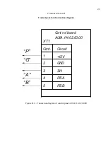
Page 42: ...ntrol panel body 5 FREE ACCESS mode control button 2 SINGLE ACCESS mode control button 6 PANIC mode control button 3 front plate 7 access direction LED display 4 LOCK mode control button 8 controller connection terminals Figure B 1 Control panel AUIA 114 02 00 00 ...

Page 43: ...tinued Annex B Control panel and connection diagram C ont 1 2 3 4 5 C ircuit 12V GND SH RS A RS B XT1 C ont rol board AUIA 114 02 00 00 P G A B Figure B 2 Connection diagram of control panel AUIA 114 02 00 00 ...

Page 44: ...44 Annex C 1 mandatory Wiring diagram of the JETPAN type turnstile ...

Page 45: ...is activated for 5 sec inp2 TO BE OPENED B in pulse mode When command is issued entry is activated for 5 sec inp3 PANIC GND of power supply common wire out3 DETECTION OF ACCESS A out4 DETECTION OF ACCESS B Signal is generated when the second last in the direction of motion IR barrier is blocked and continues for 0 2 s IN1 and IN2 with 5 sec delay Door contact 1 ACS Relay 2 ...

Page 46: ...d for 5 sec inp 2 TO BE OPENED B in pulse mode When command is issued the input is activated for 5 seconds 3 PANIC inp GND of power supply common wire out3 DETECTION OF ACCESS A out 4 DETECTION OF ACCESS B ACS Relay 1 Relay 2 IN1 and IN2 with 5 sec delay Signal is generated when the second last in the direction of motion IR barrier is blocked and continues for 0 2 s ...

Page 47: ...e mode When command is issued the input is activated for 5 sec inp 2 TO BE OPENED B in pulse mode When command is issued the input is activated for 5 seconds 3 PANIC inp GND of power supply common wire out3 DETECTION OF ACCESS A out 4 DETECTION OF ACCESS B Relay 1 Fire alarm IN1 and IN2 with 5 sec delay ...

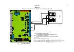
Page 48: ...48 Annex D 4 mandatory Diagram of the turnstile connection to control panel 5 4 3 2 1 P B A G ...

Reviews:

Related manuals for JETPAN